NOTE 7/2020: I have discovered a limit on how fast the saddle can be moved without losing Z counts. I assumed the limit would be above my maximum hand crank speed, but it turns out that you can lose counts even with moderately fast cranking – somewhere around 2″/sec saddle movement. For now, I manage by watching my handwheel speed, but it appears a faster uC than the MSP430 is needed. I will update when I have a solution.
12/7/22 – I just stumbled on this ESP32 Touch DRO setup on a site called Stockholmviews.com. This would most likely solve the above speed limitation since the ESP32 is much faster than the MSP430. I have not tried it yet: https://www.stockholmviews.com/wp/touchdro-diy-esp32-interface/?fbclid=IwAR0r8TOkRoQZHnrKf1z1ZNt1GjiT2w0daOuAEruxRSRDF2HHSnfO1FZsTZI
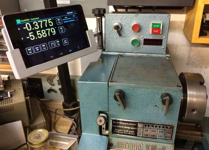
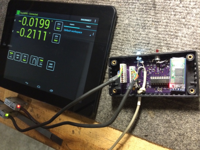
This is an outstanding machine DRO for hobbyists, not just an outstanding DIY project, but a super DRO even compared to high-end pro machines. The beauty of TouchDRO is that it uses a (cheap) Android tablet for the display and control (I used a 1st-generation Nexus tablet – $50 on eBay) while the scales connect to a small (user-built) box that wirelessly sends data to the tablet via Bluetooth. The extra cute thing about this particular DRO installation is that all that parts are very small and don’t interfere with any travel distances or setups on this already smallish machine.
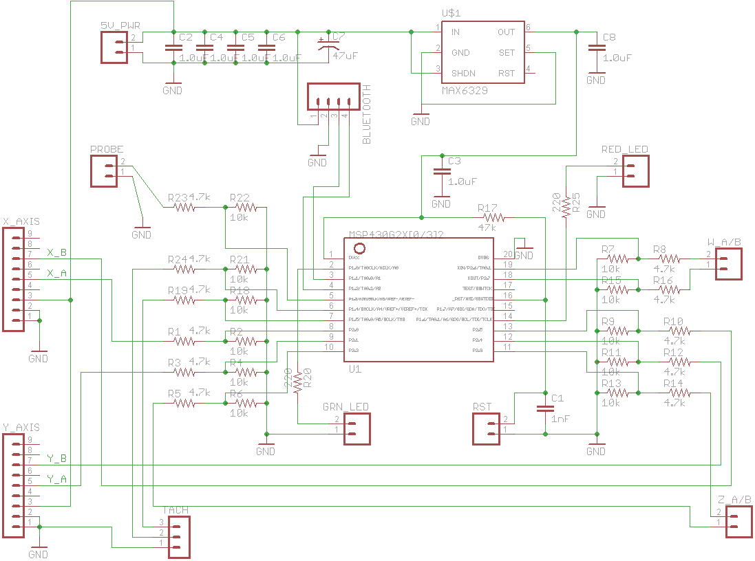
Below are a schematic and a link to the TouchDRO website.
TouchDRO Link: http://www.yuriystoys.com/p/android-dro.html
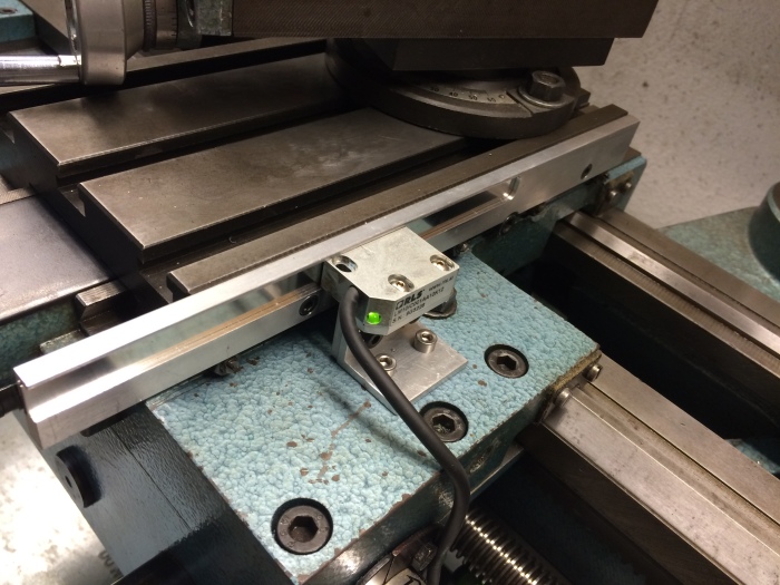
This particular circuit is designed for quadrature-output scales only. It will not work with the cheaper Chinese “caliper” or other similar scales (though TouchDRO *can* work with those as explained on their web page). Examples of quadrature output scales are optical scales and some magnetic scales. In my particular case, I used magnetic read heads made by Renishaw (Model LM10) and linear magnetic tape that I purchased used on eBay. This choice was made to get the smallest linear measurement parts possible.
Below are links to Eagle files for the above circuit. Note that you can get an MSP430 Launchpad board for less than building the above board, but I wanted tiny size and compatibility with the header connectors on my read heads, so I designed my own board and made PCBs at OSH Park.
Eagle schematic: https://dl.dropboxusercontent.com/u/2186623/MSP430_TOuchDRO_surf.sch
Eagle PCB layout: https://dl.dropboxusercontent.com/u/2186623/MSP430_TOuchDRO_surf.brd
Or, if you want to just use my layout, you can order blank PC boards from OSH Park here: https://oshpark.com/shared_projects/QH96j7xH
Read heads are Renishaw LM10s off eBay for about $100 each. These can be expensive, but I wanted the tiny size. I also got the linear magnetic scale tape off eBay. Total cost was about the same as a good Chinese DRO package like Sino.

I am interested in your conversion of the v10-p push button controls to the modified version shown on your machine. Are instructions for the modification available?
LikeLike
I’ll have to dig a bit to see what documentation I have, but I should point out that this is for a 3-phase drive. It won’t translate to a single phase motor.
LikeLike
Hi Lens,
Hi have a maximat V10 P will try to do you DRO mod. Looking good, and clean, instead of tied in chinese calipers everywhere.
Would you care to share the files ( if you have ) for the aluminum parts ?
Saves me the puzzle.
LikeLike
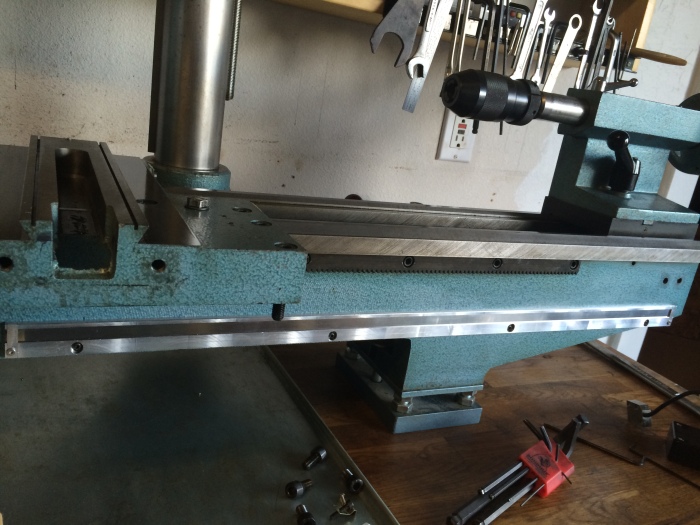
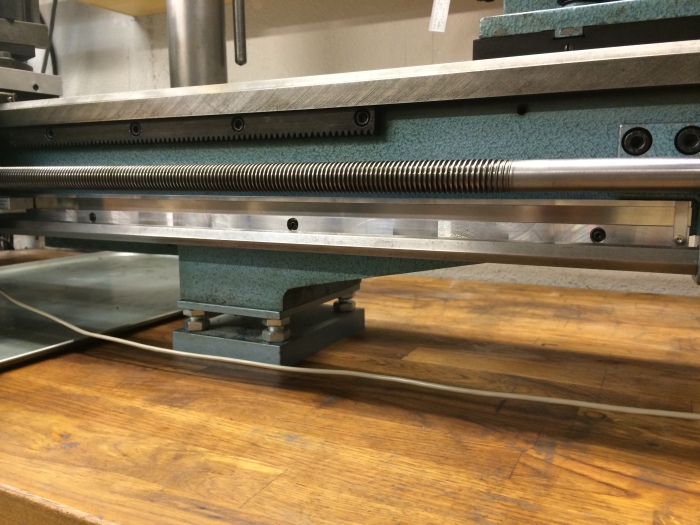
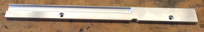
I’m afraid I just did a “fit and cut” sort of installation and made no drawings. What I can tell you is that all the mag tape support bars were made from 1″ x 0.25″ aluminum stock. I milled channels (I think about 0.12″ deep) to accept the magnetic tape. The channel width for my tape was 0.4″. I tapped holes on both the cross-slide and the bed to mount the bars. There is also a semi-circle notch in the cross-slide bar to accommodate the the lock cap screw.
One important thing you can’t see from the photos is that the bar that mounts on the bed had to be thinned a bit (down to 0.21″ I think, but you should test fit yours) so that the inside edge of the saddle did not hit it. The part that hits if you don’t shave the bar down is the back of the handwheel axle. It protrudes *just* enough to hit. It’s a bit tricky to see, but if you try to slide a 1/4″ bar between the saddle and the bed, you will see where the contact is.
What I did for installation is mark the height I wanted (between the drive bar and the leadscrew) with a Sharpie. Then I removed the leadscrew and drive bar to do the install.
I hope this helps.
LikeLike
Thank you very much for sharing the project.
I only have one doubt because everything works perfectly and it is as far as the probe
It gives me the feeling that the app still does not contemplate this option, is correct or I am wrong.
Apparently: the firm Quandrature Firmware for MSP430 LaunchPad 1.2 implements the touch probe but not the app.
I understand that the touch probe function is that when the sensor closes the circuit the app should automatically set a new source. I also understand that it will be necessary for the app to set the diameter of the touch probe sensor.
Thanks for the clarification.
LikeLike
I’m afraid I never have tried any of the probe functions. I suggest asking about that at the TouchDRO forum:
https://forum.yuriystoys.com/
LikeLike
I have been reading up on the renishaw read head and magnetic tape. Seems like a lot of versions relative to resolution , output style etc for both the readhead and tape. I can see the readhead model in the pics but what made you choose these in particular and what style magnetic tape tape did you use ?
LikeLike
Hi Mike – My choices were mostly based on eBay cost, figuring that even a low-end Renishaw setup would perform at least as well as a Chinese system. I was able to get LM10 heads for $75 at the time and the tape was $80 per meter. One meter is enough for both the bed and cross-slide on a V10P (I didn’t do the mill Z). The tape is still available at the price I paid: eBay Magnetic Tape
When I bought, I wasn’t 100% sure what resolution I’d get with “1mm or 2mm pole” tape. I wasn’t 100% sure what that meant but guessed that 1mm poles would probably give twice the resolution of 2mm, but either would probably be fine. I think I bought “2mm pole” tape and I’m still getting 0.0001 resolution. The LM10s don’t seem to be $75 any more but the heads don’t have to be those. If you search eBay for “Heidenhain LIDA 47”, there are several for $35. Heidenhain tape is available from the same seller though I doubt it’s required for their heads (though it may be cheaper).
LikeLike
Hi lens42,
I am pulling together the components to do Yuriy’s TouchDRO install on my V10, with the only difference being that I ordered one of Yuriy’s quadrature adapter boards for my application.
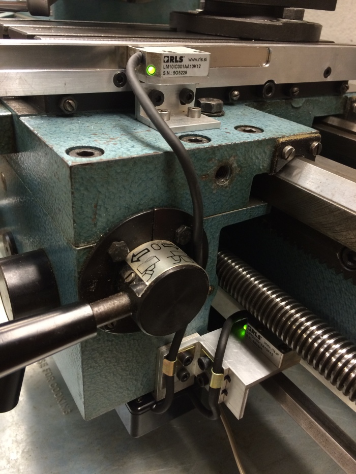
I was able to secure the same LM10 read heads that you have (LM10IC001AA10K12), and mine have what appear to be the same 9-pin Molex connectors as seen in your picture showing the PCB in the open enclosure box.
Is that picture available in a higher resolution version that you can send to me via e-mail? I was hoping to validate the pin-out of the connector to the wire colors of the LM10 to develop a ‘plug-n-play’ attachment to Yuriy’s board using 4 pin Molex connectors.
Beyond that, I have a few other questions for you that I was hoping we could discuss via e-mail, if possible.
Thanks!
Kevin J.
LikeLike
Hi lens,
Second request for the info I inquired about awhile back – having some issues with my install and would appreciate the requested info!
Regards,
Kevin
Hi lens42,
I am pulling together the components to do Yuriy’s TouchDRO install on my V10, with the only difference being that I ordered one of Yuriy’s quadrature adapter boards for my application.
I was able to secure the same LM10 read heads that you have (LM10IC001AA10K12), and mine have what appear to be the same 9-pin Molex connectors as seen in your picture showing the PCB in the open enclosure box.
Is that picture available in a higher resolution version that you can send to me via e-mail? I was hoping to validate the pin-out of the connector to the wire colors of the LM10 to develop a ‘plug-n-play’ attachment to Yuriy’s board using 4 pin Molex connectors.
Beyond that, I have a few other questions for you that I was hoping we could discuss via e-mail, if possible.
Thanks!
Kevin J.
LikeLike
Hi Kevin – Sorry for the late response. For reasons I don’t understand, I’m not always notified on comments. I don’t check WordPress regularly, so apologies for the lag. I don’t have a better photo, but from what I see it’s:
1 GRN/YEL = GND
2 WHT = also GND
3 Light Brown = +5V
4 YEL = Data A-
5 GRN = Data A+
6 RED = Data B-
7 BLU = Data B+
8 ? (can’t see color)
9 Brown (but maybe it’s gray)
The data outputs are RS485 differential, but I only used the + outputs and didn’t bother with the – ones. Yuriy’s board may take the full differential input. To be sure, I suggest just powering up the LM10 head and dragging the mag tape over while watching the outputs on a ‘scope to see that do what they should.
LikeLike
Hi Lens,
Thank you for the wiring info – it got the read heads up and running, but the calibration process has been frustrating…
All read head lights are green – using Yuriy’s 1-2-3 block scale calibration process shows almost 1/8” over 3.000 on the X axis; less than a thou under on the Y, and almost .25 off on the Z.
I can play with the CPI numbers to get to 3.000, but reversing the cal process does not go back to 0.0000.
I know that Yuriy’s magnetic scale page mentioned that some of the Chinesium mag scales may have quality issues – I got mine off of eBay, but I never saved any specs, if they had them. Doing a 1” test shows 8470-ish CPI, when Yuriy’s info shows 1 micron mag scales at 25400 CPI per inch, and 5 micron at 5080…
Yuriy’s board did call for the – A/B terminals, so I utilized those. The Renishaw literature for the LM read heads has some info that I would like to discuss with you… can you email me at kwski@hcc.net so I can send the .pdf’s to answer some questions I have?
No need to post this in the comments.
Regards,
Kevin
LikeLike
Hi
This is a super article and sure will help me fitting a DRO to the V10P that I have. Would it be possible to have a copy of the aluminium parts designs you made as they looks too neat…Thanks for any help.
regards
LikeLike
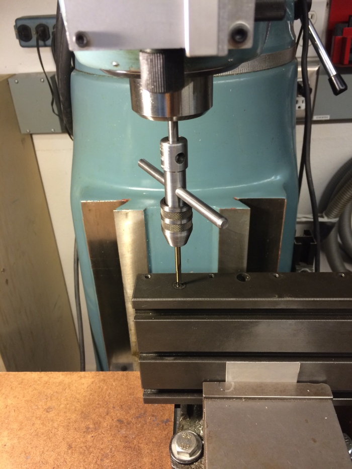
HI. Unfortunately I didn’t make any drawing for the parts. I just cut them to fit. The most important cut was shaving some thickness from the 0.25″ thick rail on the bed so that the saddle can slide over it without hitting. The mounting holes were tapped into the machine so I used the parts as guides to drill holes.
LikeLike
Len
I’ve picked up on your idea and am in the process of implementing TouchDRO on my V10P using your ideas as a starting point (you will have seen my comments over on the V10lathegroup).
I went for even smaller readers based on the RLS RLB module and their 5mm tape. I particularly wanted the third axis on the milling attachment, which kind of negated the benefit of having all the electronics on the apron, given only a single BT connection to the display. So my overall layout will be somewhat different in detail.
I also opted for 1um readers on all axes, since the price was the same. However, when I started experimenting with Yuri’s MSP340 implementation, I determined that it runs out of oomph and starts missing pulses at around 50khz, which on a1um scale Is 50mm/sec, and since installing my prototype just today, I quickly saw that a reasonably fast handwheel move of the carriage does indeed result in significant lerror (but slow is good, with a repeatability of 1-2 um against the carriage stop).
I note that your display is 0.0001” so I am guessing that you should be dropping counts at about 5-6 inches per sec, which is quite fast, but not ridiculously so. I can easily move the length of the bed in 2 sec or so.
Do you indeed see this?
Roman O.
LikeLike
Hi Roman. Well I went and check this tonight and you are absolutely correct. If I crank the handwheel quickly, probably about 2 RPS, the DRO loses position. It’s pretty dramatic, and can even freeze when I’m cranking fast. Thanks for pointing this out. I never realized this. Are you planning on living with it, or fixing with better hardware?
LikeLike
Len,
I have some time ago bought a faster processor, spent some time reverse engineering the (admittedly simple) interface to the BT module, and am starting to work on the software. I’m hoping it will be fairly straight forward because, as it happens, the processor (STM32F407), even though it is 32bit CPU running at around 100MHz, will end up idling since it has hardware quadrature decoders hanging off 32 bit counters, built in. And way cheaper than a Launchpad at around $10 postage paid from China. I progress slowly because I have a number of projects on the go ( I bought my stuff from RLS well over a year ago!) but this is becoming my priority evening task.
In the interim, I propose to use the Launchpad as is and wind slowly.
I’ll let you know how I go.
Roman o
LikeLike
Len,
An update on progress so far. I have prototype software running well on an ESP32 which is fast (240MHz), dual core, has integrated Bluetooth, and is cheap and easy to use on the Arduino environment I am familiar with. Speed-wise, orders of magnitude faster than Launchpad. I am about to install the prototype on my lathe and use it for a bit to flush out any issues.
Yuri’s TouchDRO has provision for up to 4 quadrature encoders plus a tacho. I am not sure how the tacho fits in or how it’s handled, so I haven’t implemented this. Yet.
I guess to use it one will need to be at least slightly familiar with the Arduino world in order to program it. Is that a problem?
Roman
LikeLike
Roman – I’m OK with the Arduino world. Lately I’ve noticed cases where I’ve lost counts at moderate (i.e .not trying to go fast but just doing normal work) cranking speed. I may have some new issue (alignment or something), or maybe I’ve never noticed the errors before. In any case, I am much more interested in fixing this, now that I’ve actually screwed up some work. Can you send or point me you your design somewhere?
LikeLike
Len, I expect that you have seen my message on your site saying that I have posted the software to github, and I have also posted a bunch of photos on the emcov10 lathes group site. I am more than happy to talk about this project at great length, but without knowing where you are coming from, I’m not sure how best to address your question re “my design”. In a nutshell, the ESP32 board (Doit ESP32 DEVKIT V1) replaces the launchpad-based unit that Yuri has on his site (including the Bluetooth card) pretty much as a black box replacement (albeit following some configuration in the source code which I hope is explained adequately therein). It includes tacho functionality which has been bench tested but not on an a actual spindle, so it may have some real world quirks which I would be happy to address if someone discovers them. In my particular case, because of the encoders I selected, I also made some differential line drivers to fit under the carriage, and line receivers to sit in front of the ESP32 which is mounted near the base of the milling attachment, in a box which also accepts the output of the vertical attachment encoder and also has provision for a probe input. These aspects of the design are completely straightforward. The carriage was also going to be dragging a wire, so I figured whether that wire was 2 conductors (power only) or 22 conductors (bunches of differential signals) made no real difference. The BT connection appears quite robust, and connects automatically on switch-on before I even notice. Since I have lots of computing power, I am planning to add a small display (my ESP32 box has a clear cover) to show such things as encoder error status (particular to my encoder) and maybe some other parameters that I haven’t thought about yet. And I want to add some way of using the encoder’s index pulse to recover absolute position on power-on; all still on my to-do list.
Though I wish it were otherwise, I’m not sufficiently web-aware to be one of those many people, like yourself, who manage to post such things in minute, illustrated detail. Maybe one day I will bite the bullet and establish a web site like yours. But In the meantime, I’m happy to share any specifics that you, or indeed anyone else, might want.
Hope this helps Roman
>>
LikeLike
Thanks. I ordered a few ESP32s and will see if I can get one running in place of the MSP430. If I hit a bump, I’ll let you know. I don’t need the tach. Re this blog, I started it mostly as my own notebook, and also find that when answering a question, it’s better for me to put information here and link to it, rather than directly posting to Facebook or a forum, which sometimes don’t last.
LikeLike
Hi Lens,
Thank you for sharing your great design. I found your project while I was searching for compact scales, and I’m super glad I found this write-up. In the last 24 hours I’ve gone from knowing nothing at all about DROs, to getting a handle on types of scales, vendor compatibility, and costs. I just picked up an 8×14 lathe, and the seller had put a Sino SNS-2V readout on it, but there were no scales. Down the rabbit hole I went… having been a machist & fabricator in a previous life (20 years ago, but I still do alot of random stuff), I quickly realized the Sino isn’t worth much on its own, so I’d be replacing it and fabbing smaller magnetic scales. You’re leading me to Yuriy’s site and TouchDRO is a miracle!
Roman,
I’m going to use the RLS RLB encoders too. My 8×14 lathe has so little room on it, and upon filling out the order form I’m suprised how inexpensive they are. I’m super excited to have found parts to build scales to fitthis little lathe instead of having to make wonky brackets for big glass scales.
I’m now researching the TouchDRO Scale Adapters, and I think that all I’ll need are the RLB or RLC2IC encoders, 5mm scales (prob get them a little longer than needed and cut the non-refernced end if necessary), and the scall adapter kit (and scale mounting/etc). If you have any pointers to a guide or other suggestions then please lob ’em at me!
Thanks again!
–Justin
LikeLike
Justin,
I have posted a bunch of photos of my dro installation at https://groups.io/g/emcoV10lathe/album?id=249765. This project took me awhile – I bought the RLS bits at the very start and built the rest around them. The 5mm scale don’t have a reference end as far as I can see. I selected 1um resolution, even though you can get much finer. The trade off is the count rate – even at 1um resolution the “normal” TouchDRO Thinkpad hardware struggles to keep up, so I had to make a faster front end.
Anyway, have a look at my photos. They may trigger specific questions, which I will be happy to answer, if I can.
Roman
LikeLike