This is a repair of Bose L1 tower PA system. These skinny tower speakers are somewhat of a marvel because they are designed to stand behind the musician (aimed RIGHT AT the microphone) and don’t generate feedback (in most situations). Ah, the miracles of DSP.
It turns out these PA’s have a frequent failure in their power supply. Read on for details.

UPDATE 2/13/2024: For those who want to crack open their dead L1, can do basic soldering, but struggle with troubleshooting electronics, or don’t have test equipment. Here is a list of parts I’ve replaced and their Digikey part numbers. Most repairs don’t involved all of these (usually only two or three), but since the parts are not that expensive, you could shotgun all of them and stand a decent chance of getting an aux power board back up.
- D605, D606, D607, D608, D609: Digikey part # 497-3216-1-ND
- C610: Digikey part # 493-13294-1-ND
- Z601: Digikey part # BZX55C18-TRGICT-ND
- D601: Digikey part # UF4006CT-ND
- R614: Digikey part # CF14JT22R0CT-ND
- R621: Digikey part # A138094CT-ND
- R620: Digikey part # CF14JT1K20CT-ND
- Q601: Digikey part # 497-STFU10NK60Z-ND
(Note that in the comments I messed up the part number for Z601. It’s correct in the above list)
UPDATE 10/22/2021: Since I first published this, I’ve gotten a lot of inquiries from people regarding repairing their L1s. For people local to northern CA, I’ve swapped working units for their bad ones plus cash. Then I try to fix the dead one I took in trade. All together now I’ve worked on five units and succeeded fixing all of them. I’ve also successfully repaired an aux supply board that someone extracted from their L1 and sent to me (Unit 3 below). For those trying repairs at home, here are my results (I’ll try to update as I see more units):
6 of 7 failures have been in the “Auxiliary Power Supply Board” (read below for more details). I recommend starting trouble shooting there if you L1 does not power up but please note the dangers of troubleshooting circuits that are hot to the AC line (noted elsewhere in this post).
Unit 1: My first attempted repair which started this blog post – D608 open – REPAIRED
Unit 2: D601 and D608 bad – REPAIRED
Unit 3: D601 bad – REPAIRED
Unit 4: D609 bad but also Transformer T601 open between pins 6 and 8. I was lucky in finding a broken wire that was accessible outside the windings. I reconnected the wire with some very carefully soldering. – REPAIRED
Unit 5: Had a working Aux Supply, but no sound from one half of the tower. The +/-27 power supply (there are three) for that channel power amp had smoked MOSFETs and other components. I harvested a +/-27V module from Unit 4 to get this one out the door, then repaired the supply by replacing two MOSFETs, two zeners, several resistors, and one rectifier.
Unit 6: A bit of a train wreck with many visibly charred components. I ultimately had to replace D606, D602, D614, Q601, R614, R620, R621, SCR601, TH603 and Z601. Whew! But now back from the dead. – REPAIRED
Unit 7: replaced D602 and D607 – REPAIRED
Tally so far on L1 repair is 7 for 7!
Back to the original blog post:
The tower speakers slide into the base where they are both supported and electrically connected to the amplifier. All the circuitry is in the base.
The bad news is if you have a problem with this first generation L1 (ours is about 10 years old), Bose is zero help. They will no longer repair them and only implore you to get a new system. To make matters worse they are completely uncooperative about supplying schematics (though I was able to find documentation on-line).
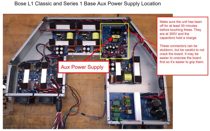
Our L1 suffered a power supply failure, which is apparently fairly common as these units age. The culprit is the “Aux Power Supply” shown in the block diagram at this link.
The below linked doc has schematics and instructions for disassembly. Even though it provides guidance, I still recommend taking LOTs of pictures. Especially of where connectors plug in.
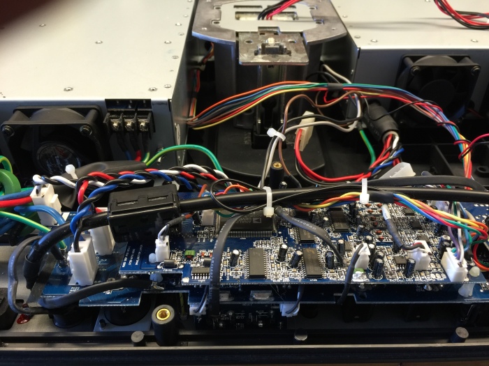
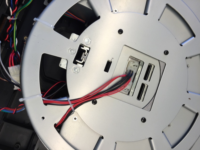
Dissembling the base is no small task. There are screws everywhere, and you have to pull almost everything apart to get at anything useful. Below shows the top cover and control panel PCB after unplugging from the power chassis.
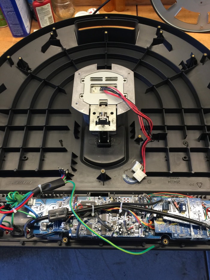
Pull the U-shaped top cover and you are in.
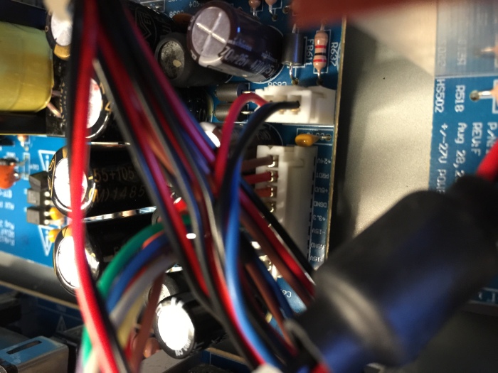
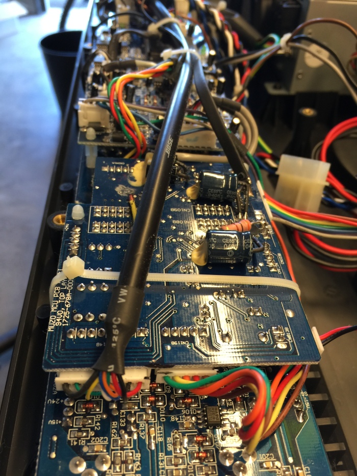
 I pulled out the Aux Power Supply board (upper right corner) and the EMI filter board (lower right corner) in order to troubleshoot the power supply on the bench.
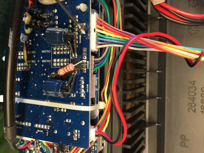
HUGE WARNING! The EMI filter board and large parts of the Aux power supply are NOT isolated from the AC line! I powered this from an isolation transformer before hooking an oscilloscope. Make sure you fully understand what this means before proceeding with any testing. Unisolated circuits are VERY dangerous to work on.
Warning #2! The output of the EMI board is about 330V and the big capacitors on that board can store that voltage for up to 30 minutes time after the base is unplugged. Check that the voltage has fallen to a safe level (<20V) before touching anything or removing any boards.

Aux power supply board
I found some unrectified AC waveforms in places that should have been DC, and pinpointed the problem to a large rectifier diode that was open-circuit. After replacing this diode, all the Aux rails powered up, but many voltages were off (by 5V or more) from the spec’d values. I spent several days chasing this with no progress, until I guessed that the amplifier and the rest of the L1 circuitry might need to be connected to the Aux rails before they would read the correct voltages. This turned out to be correct. When I assembled and temporarily wired everything together, the Aux voltages read correctly. These rails are not tightly regulated and needed the load of the circuitry to pull them to their proper voltages.
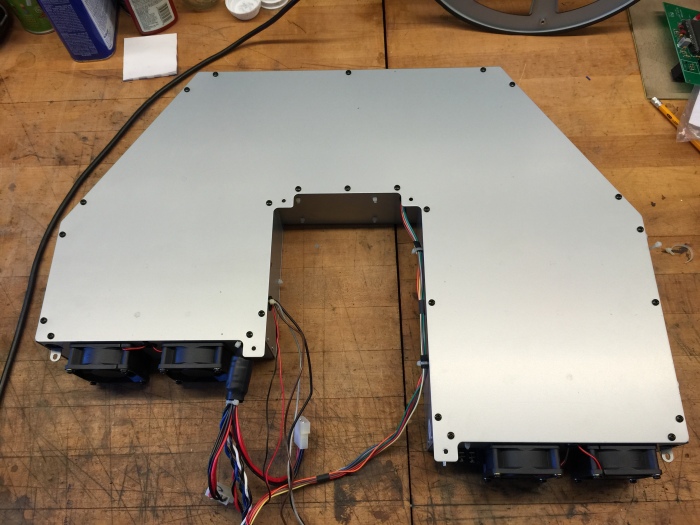
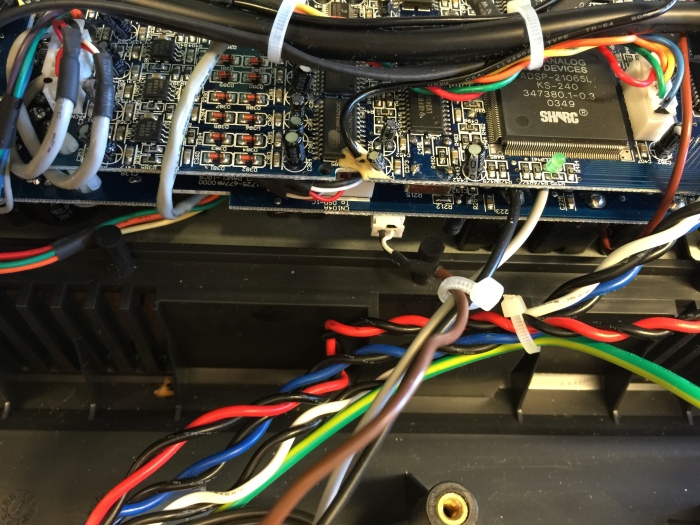
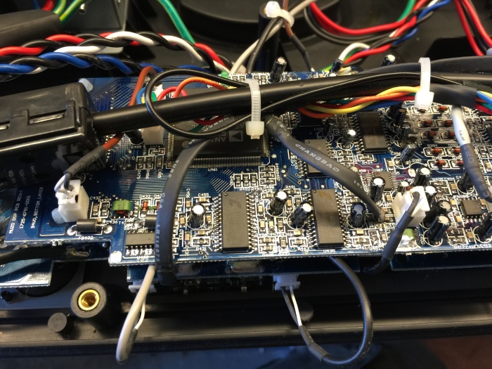
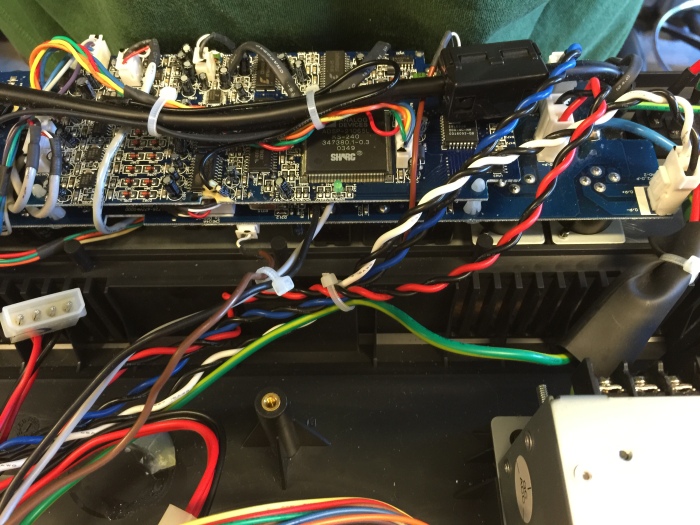
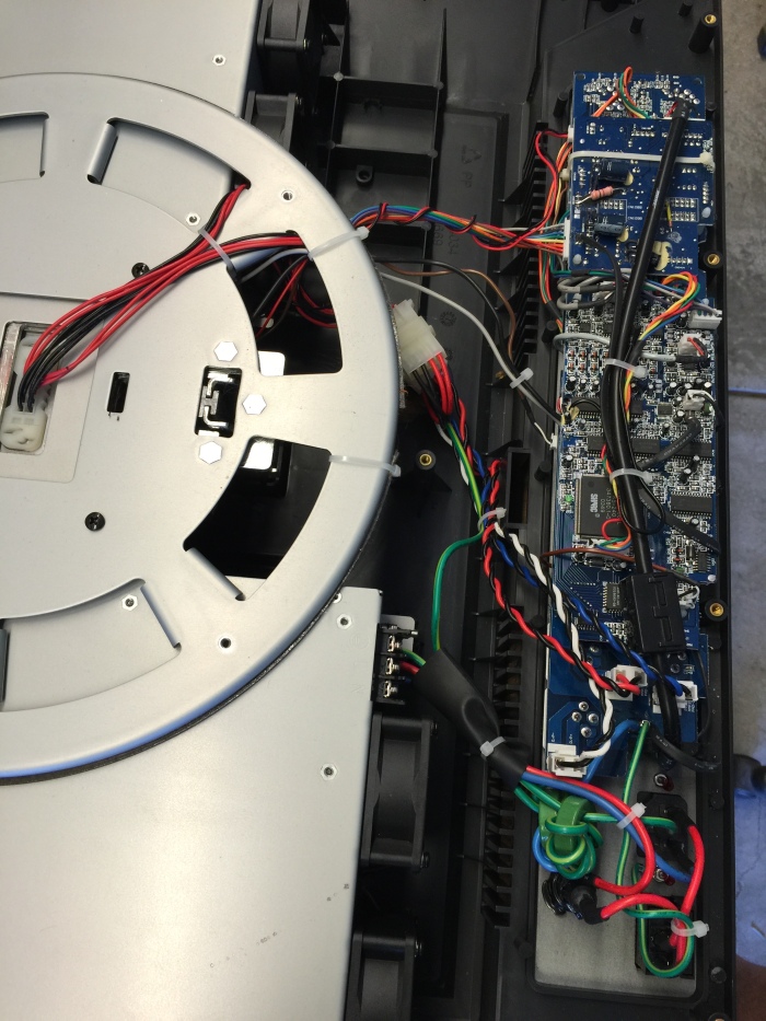
Other miscellaneous inside images below, mostly to remind me where all the connectors go:


Thanks so much for posting these details and circuits. Enough for me to repair a faulty aux power supply in my LS1 over in the UK. D606 and D601 both failed short, replaced and we’re back up and running. Would have been much more difficult without your guidance and inspiration.
LikeLike
Hi, if it’s of any help, here’s a UK-based guy who repairs Bose stuff that in my experience no-one else will touch. He’s been a great “last resort” help to me in the past. Cheers.
https://community.enginedj.com/t/im-here-hello-all-clive-crs1-uk/1828
LikeLike
I have a dead unit. Was wondering if I could send to you for repair? I’m in Pennsylvania.
LikeLike
Hi Jason – My experience is that it is not practical to ship these things for repair. The last time I checked it was close to $100 each way, and I expect I will be more now. Also, there is a high chance of shipping damage. If you can find some magically cheap shipping, I’d consider it, but so far I have only worked on units that people have brought me.
LikeLike
Hello lens42 –
Can I power the Bose L1 (first gen) tower and bass cab with a different amp/processor/etc…much like a Bose rack mount amp setup? Basically bypassing the old heavy base. Mine still work great but I’m noticing a noise when I power down on ne of my units. Might be an indicator of bad things to come.
Thx
Mark
LikeLike
Superb advice – D606 and 601 restored the power – can be monitored at 8 pin multicoloured connector CN4098 when in situ (+15V, 0V, -15V, +3.3V, 0V, 5V, Fault, +24V). Still to diagnose deeper Fault on my L1 Model 1 – any hint on how the ‘fault’ voltage rolls or why all voltages are ok but no power LED green/red – there was once after the Aux PSU was first powered up but no more … thanks in advance – I’ll get the meter and scope out about the power amps and psu’s
LikeLike
Hi Peter – The power amps have their own separate +/-27V supplies, but I’m not sure if a failure in one of those will lock our the power LED.
LikeLike
Len,
First off, thank you for this great head start on getting this power supply to work. I have had mixed success with mine, in that, the voltages are there, but not quite to spec: (+11.46, -14.38, 3.68, 7.13, and 18.8V). I have changed out most of the troublesome diodes (D606 was originally a dead short), and otherwise pulled every suspicious component, checking them all with my LCR meter. My spidey-senses say it’s IC603, but I cant prove it.
Do you have any advice as to where I should focus my scrutiny?
Thanks again
LikeLike
Andrew – I mentioned in my blog post that it’s normal to get odd voltages if you run the aux power board with no loads connected. Are you are getting these voltages readings with loads connected or unconnected? If unconnected, you may have fixed it and the outputs will be their correct values when the loads are hooked up.
LikeLike
Hi, thanks for the reply. My Model 1 saga continues (here in UK) now that the aux psu is repaired and all voltages are thereabouts, note the aux psu also sets the power amp voltages (all 7 voltages rely on a single TL431 regulator and a few zeners). Referring to the Digital Signal Processor PCB Rev J, Mic analogue signals disappear into U302 TC9459F volume control and line analogue signals disappear into U385 A/D converter pins 16/17 and 20/21. Although clock signals are present, there is no analogue signal out from U388 2/3 or 5/6. So my problem lies in digital terrain. Has anyone else tried by passing the digital equalisation by connecting CN104B pins 1 & 3 through a couple of resistors to CN115B pin 3? It seemed to work (I don’t have or need a bass unit) and my external mixer can add some equalisation & lpf etc.! PS the non-operating power led is driven from pins 44 & 45 of the mcu via CN119A/B. Maybe I’ll rebox it and the night fairy will reboot it good!
LikeLike
Peter – You have drilled into the digital parts of these amps far further than I. Nice work. If you feel adventurous, the CS5361 (U385) chip can probably be replaced with some careful soldering, but your bypass solution seems reasonable also, and a lot less work.
LikeLike
I bought two of these Bose units new in 2003. I sold one about five years ago when it was working. I hadn’t fired up the other one for a few years, fearing the worst with all of the talk about these failures.
To my surprise, it came on and sounded great….for about 6 hours… then it died. Can’t wait to try the diode replacements to see how things go. It’s too nice of a system to not at least give it a go!!!
LikeLike
When you get it open, first check the voltages on the aux power board outputs.
LikeLike
If I can’t get my system working, do you have any idea where the crossover point is between sticks and subs? I may try to power them with other amplifiers which would require known crossover values.
LikeLike
I was wondering if you are excepting units to repair?
The shipping price is of no problem for me.
Or
Can I send the aux supply?
Or if I turn this unit on can I report what I see to you and receive further debugging instructions?
I have an electronics background and completed the diodes and capacitors replacement to no avail.
I noticed this device is a mobius design in that controls go back and forth from board to board which makes it very difficult to troubleshoot for me.
Thank you for any advice.
LikeLike
Do you have the values of the components said above
Or better yet can I buy it from you?
Please let me know thank you!
John
LikeLiked by 1 person
Here is a list of parts I’ve replaced and their Digikey part numbers. Not all repairs have involved all of these (most need only two or three), but I guess since they are not that expensive, you could shotgun them all and stand a decent chance of getting an aux power board back up.
D605, D606, D607, D608, D609: Digikey part # 497-3216-1-ND
C610: Digikey part # 493-13294-1-ND
Z601: Digikey part # BZX55C18-TRG1CT-ND
D601: Digikey part # UF4006CT-ND
R614: Digikey part # CF14JT22R0CT-ND
R621: Digikey part # A138094CT-ND
R620: Digikey part # CF14JT1K20CT-ND
Q601: Digikey part # 497-STFU10NK60Z-ND
LikeLiked by 1 person
regarding BZX55C18-TRG1CT-ND
i could not find. i could find this, but the BZX55C18-TRGICT-ND (the 1 is an I)
I’m going to shotgun it, i don’t have isolation or an oscilloscope, just gonna swap all the culprits and pray.
is this the right part?
thanks for this excellent post.
LikeLike
i just want to know if you were manually typing these part numbers, and the “L/1” is a legit typo, and i can know i ordered the correct diode before i start to desolder this board.
thank you so much.
LikeLike
sorry it was a upper case “i,” not “L.” it’s not a “1,” that part does not exist. did i order the right thing?
LikeLike
Yes, Tuna. You are right. The “1” is really an “I”. The part is an 18V zener diode. Sorry about the typo.
LikeLike
I have gotten my unit to power on correctly play through one half of the cylinder. Amp #2 has a no go output.
My unit failure stemmed from continuous low power use meaning I dont drive it hard or loud.
I repaired the aux and emi power supply boards with this of parts.
The lower cylinder +-27vdc power supply was not working. I replaced the 18v zeners, 2n3904-2n3906 transistors and d508-1n4148 as there was a fault condition. I tested all but felt there was a failure loop somewhere.
The +-27vdc boards all receive +27vdc but use a PWM setup to generate the negative 27vdc. On the scope I saw the chip UC2842B at pin 6 was not producing the necessary clocking to drive the t501. I replaced.
LikeLike
Not sure I agree with your conclusions. There is no way “continuous low power” is harmful to the L1. Whoever told you that is way off base. Also, I’m not sure why you say only the -27V is PWM generated. Both supplies are generated by the UC2842B by way of the two 2ndary taps on T503. If you are getting +27V then the supply is mostly alive. You wouldn’t get +27V if any of the line-side or UC2842B circuitry was dead. Have you tried running the +/-27V supply board with no load connected? Maybe the amp board is overloading the -27V rail? If there is no -27V with no load, then there are only a small number of components to check – those between T503 and the -27V output. My guess would be D504 or a shorted capacitor.
LikeLike
Thank you for you help.
I was just anecdoting the negative 27vdc side of my adventure. This works.
I am working on the next problem in the amplifier #2 which was my next post.
Do you have the Amplifier rev: I schematic?
LikeLike
I have all the schematics printed out. All the PCB revisions match except the amplifier board. I have MUZO D AMP PCB 1725-679A-001 rev: I.
Here is a pic.
https://www.amazon.com/photos/shared/hx_MeiHZSeOfJeNG7XExEA.J89YHGXjD2AFPWmdeIz6WX
Does anybody have this revision: (I) schematic?
Thank you.
LikeLike
I was gifted an old Bose m1 s1 classic system. When I powered it on initially, I got nothing out of the speakers but showed signal to the channel. I unplugged the xlr cord from channel one then plugged it back in and then got only static through the speakers. Would you have any idea what my problem might be?
LikeLike
Sorry, I don’t know what that is and couldn’t find it with a quick search. Can you provide more details? I had a similar problem with an L1 Compact system, that I sent back to Bose and they could not fix it, so they gave me decent credit toward a new system. Of course you should check the cable and the jack.
LikeLike
I apologize. I meant L1 Model 1.
LikeLike
Russell, I sent you an email with the block diagram. Try inputting or taking output signals from different points in the signal path to pinpoint where the issue is.
LikeLike
Thought I would make this public:
I have the amplifier board rev I and no schematics can be found. What is very strange is the previous revision and the next revision J show three chips for each of the 3 amps. The Rev I board has only the 2 audio amplifier chips per heat sink with no main chip controlling the two. Very obvious on the schematics but each amp on that one board show no controller.
Thank you for the help. I am not giving up just yet. My next step is to just replace the chips and see what needs attention next. I could not have gotten here without the Power supplies working. So I have progress from a dead unit to at least one segment of the cylinder working. There is signal clipping on high levels of input. I have not attached the bass woofer yet either. One step at a time.
I will report progress as I go.
LikeLike
Thanks for your help. I found the next problem.
The versions of the amplifier schematic are close enough to track down the problem using datasheets and rev G schematic.
I was hesitant to lift the amplifier board out of the chassis as the heatsinks are live voltage. But this last bit of repair was only achievable with this board lifted. I then found the TDA8929T SOT 24 controller chips with all the other surface mount there. I tracked down the signal path in the bottom cylinder amplifier part of the board which is the middle section. The TDA8929T does not pass a signal from pins 4/8 to 13/24 like the two other controllers do.
My question now is do you offer SMT repair if I purchase the chips and send the board with parts to you? The shipping would be very inexpensive.
Thanks again.
LikeLike
Hello, I have been troubleshooting my L one all day long. It is blowing the fuse as soon as the power is turned on! I’ve got it in there down to the auxiliary power board and the 27 V board next to it if those two boards are disconnected fuse will not blow as soon as I connect either one of those it blows the fuse any help would be greatly appreciated.
LikeLike
Can you narrow it down to which one is at fault? Try connecting ONLY the Aux Power board or ONLY the +/-27V board. There actually should be two or three +/-27V boards, depending on model. Once you get it down to one board blowing fuses, then we can proceed. If either board blows fuses by itself, then both would appear bad. I have fixed both of these boards in the past, but the symptom was always no power LED and of course no sound, not blown fuses, so your issue may be different. The good news is that more violent problems like that are usually easier to find.
LikeLike
In trying to replace the surface mount amp chips I found that the boards are only good for single wave soldering manuf. The pads are held on very weakly. The copper is very thin. I found this on other boards too. I previously had this somewhat repaired then the amp chips blew after I replace the ps components and a pwm controller chip. I have to ditch this garbage for a DPS amp that is better supported by the manuf.
B)uy O)ther S)ound E)quip was the most explicit advice I received.
I am not going to do any further repairs as once I get this one repaired and put back together another failure is coming and I am not repeating this effort. So why bother. Just because I can perform this doesnt mean I should.
Thank you all for your responses here. It has been an adventure.
LikeLike
The unit now works.
I got the amp #2 TDA8929 controller chip replaced by Global Electronic Service. I then had the #1 and #3 TDA8929’s replaced by Len. I then replaced the amp#2 TDA8927 pairs. Using this unit as a pc speaker system has its down fall as the pc puts out a lot of noise and activity. The Bose amplifies it very obvious. Now I can reassemble to monstrosity back into a usable unit.
Thank you all for your help here.
LikeLike
I have an L1 model 1 with a broken end cap #3 on the lower speaker. (the cover on my car-top carrier got snapped off and hit the end of the speaker as it flew away). Can I get just that part? It all still works.
LikeLike
Played a duo acoustic show the other night with my L1 and every single channel cut out and came back up at different times during the gig… at first I thought it was a bad guitar cable when my acoustic went out and came back up 10 seconds later, and then my mic went out for a good 10 seconds, and then later on my lead guitar player’s mic & acoustic also went down for a few seconds.
Any experience with these kind of issues? Powers up just fine and seems to be ok outside of the intermittent outages.
LikeLike
This is a new one to me. The channels are pretty independent. You can sometimes isolate problems by inputting signals or checking outputs at different jacks. Did it happen early in the gig or late? Late might point to some thermal problem. It’s going to be tough to figure out unless you can make it happen again.
LikeLike
Really appreciate the response. Playing at a different venue this weekend so I’ll let you know if it happens again.
LikeLike
My L1 turns on and the mic and guitar signals light up but no sound! The speakers click in nicely. I rebooted by pulling out power chord and turning the unit off. When I turned it back on everything worked fine…until I turned it on again the next day. Rebooted 20 times but nothing! Any suggestions?
Robertipp56@yahoo.com
LikeLike
All I can think of is to try some of the downstream inputs (check the block diagram) and see if you can isolate the part of the chain that’s not working. Looking at the line outputs can also help with same thing. I haven’t looked at much outside of the power supplies, but I know of one person who replaced a power amp IC.
LikeLike
I replaced the PWM on one of the amp power supplies. I had to eventually give up as there was a cascading round robin loop of failures when replacing the ‘next’ chip. I realized that I would have to replace all ics in the signal chain to alleviate any more problems and the thinly made circuit boards were not worth the insanity or price. I removed all the amps and their power supplies replacing the function with 2 Behringer NX1000Ds. I rewired the base unit by pulling the red, white amplifier lines that ran to the panel jacks and wired them to the upper and lower sections of the linear array. The connectors are standard personal computer power connectors of the original types that connect to floppy and hard drives. The Behringer units connect directly to the panel now through the Speakon Twist lock jacks. I lost portability but now my system is back and I am happy. Total cost of the Behringers was $800 but I salvaged the speakers and added another Bass module.
LikeLike
I would like to see pictures and/or diagrams of the Behringer nx1000d usage. I am very interested in bypassing the 1st Gen L1 base units and powering the towers and “subs” w an external Amp. Thx Mark
Sent from Yahoo Mail on Android
LikeLike
Do you have your unit disassembled?
There is a picture above showing the top of the base unit with the linear array connectors coming out. This is where you start. Get an old PC power supply and cut the connectors at the Power supply with their full length of cables. Then on the Bose amplifier board desolder the 3 pairs of black/ Red/ Blue/White wire pairs. I use nylon terminal blocks to connect those to the speakon twist jack connectors. The beauty of this is the amp out pairs connections do not go any where else on the panel board but to the jacks on the panel. Of the 3 pick just two. I pick the two that are side by side in the gray/white part of the panel.
Remove the line power connectors from the side of the Bose unit metal casing and tape off individually to keep power off permanently. This will make the line plug and power switch useless as that is not needed.
LikeLike
Post an email for pics.
LikeLike
When you put the unit back together snake the array cables flat because the plastic housing will crush them. You’ll see. Mine were crushed upon manufacturing. The whole design puts the units whole weight on these in the feed lanes. When I saw this at the end of this adventure I knew gutting the unit was the best thing to do.
What I did was find the open path and put down a section carpenter’s tape, then laid the Linear array cables flat on that and put a swipe of hot glue over them to insure flatness.
LikeLike
I have a L1 Model1 with no remote, bass module, etc. I rebuilt the Auxiliary board. It plays great ( for a Bose, however the power light stays AMBER… Am I still in trouble?
Thank you, Richard
LikeLike
Not sure. Maybe the check the voltages out of the aux board to see if they are on target. I don’t think there is any additional harm in just running it until it dies, if it ever does, unless of course you are gigging in a situation where it would be bad if it failed while away from home.
LikeLike
Hi folks – I want to get in contact to the old “analog” guy – and technicians around. I reed a lot of articles – funny – my problem is a BOSE L1 – Model1 with no bass module – a lot of trouble. More next – regards Mike from Munich
LikeLike
bonsoir a tous je cherche quelqu’un pour réparer mon socle bose l1 il ne s’allume plus si vous etes en region IDF je peux me deplacer je payerait bien sur pour la reparation merci a tous
LikeLike
Hi Len, I just found your website and glad I found it.
I have a Bose L1 that is not working. I proceeded opening the base. I measured filter output which was about 330V that worried me (now I see your article confirmed that it is ok). I proceeded checking that board. I suspected rectifier issue, opened it and measure it with multimeter and it was fine. I put it back and now starting to suspect Aux board. But at this point I’d rather use your service if you are in SF bay area and have time to work on my unit. I can drop it anywhere from San Jose to Martinez (sometimes going that way for other reason).
Thank you for your consideration.
Andy
LikeLike
Hi Len, I have a Bose L1 power unit that does not turn on. I have opened it up and tested the output leads of the PS with no luck. I’m interested in your repair services, if they are available. I’m local to the SF bay area and can bring it by.
LikeLike