My wife is a life-long musician, playing mostly stringed instruments, but has gotten into theremins in the last few years. I won’t go deep into what a theremin is, except to say it’s an electronic instrument invented in 1920 by a Russian physicist named Leon Theremin. There is a wealth of information online. If interested, you can start here: https://en.wikipedia.org/wiki/Theremin
Most theremins are purely analog instruments. This can make them somewhat finicky to set up, and sometimes challenging to get the result a player is trying to achieve. The D-Lev is a modern digital implementation that retains the original theremin’s analog control, but employs digital means to improve stability and linearity, as well as add multiple “voices” and other neat features that make a theremin more playable.
D-Lev is an open source project developed by Eric Wallen, and described in detail at: https://d-lev.com/. I discovered it while researching problems we were having with our Moog Claravox. The Claravox was “supposed” to be the ultimate theremin from Moog, a company that has been synonymous with theremins and synths in the modern era. I don’t know if it was Eric’s intent, but the D-Lev seems to be the instrument that Moog *should* have made.

As yet, there is no manufacturer making D-Levs for sale, so your only option is to build one or get someone to build it for you. Eric Wallen sometimes provides the pieces for assembling the D-Lev as a kit, but I opted to build from scratch because my wife had specific requests which required design changes. Eric’s design employs multiple boards in order to be flexible enough so that a buyer can fit it into the case of their choice. Many examples from builders, such as wine boxes and Pelican cases, are shown on D-Lev.com. I got significant inspiration and some design guidance from Roger Hess and his particularly polished builds.
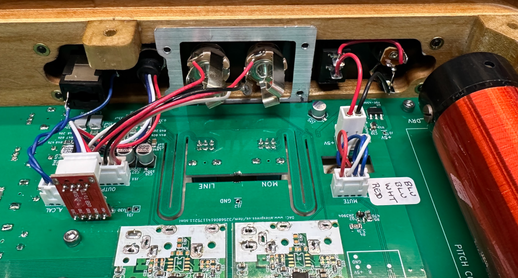
I ended up combining the schematics from the five boards that make the D-Lev kit into one PCB, eliminating most connectors and simplifying coil mounting and mechanical assembly. The downside to this approach was that a one-board design locks in the positions of the displays and controls. I opted for mostly surface-mount parts, despite having enough room for through-hole components, because I prefer working with surface mount parts. I can solder “en masse” with hot air or a hot plate, and don’t have to clip leads. I mostly used large (for surface mount) 1206 resistors and capacitors because they can be hand soldered in a pinch, especially with the “hand solder” surface mount footprints in KiCad.
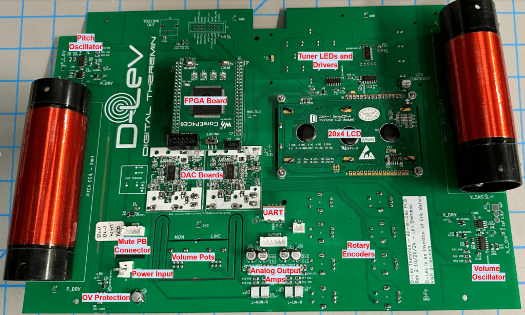
A few tricks were needed to get controls and displays with different heights to fit up behind a single flat front panel. The encoders and volume pots had different heights so I laid out a flexible “snake” routing in the PBC that allowed the pots to sit a few mm lower than the main board without requiring a connector.

The board was created in KiCad. KiCad files and Gerbers are available here: https://github.com/lens42/D-Lev-All-in-One-PCB/tree/main
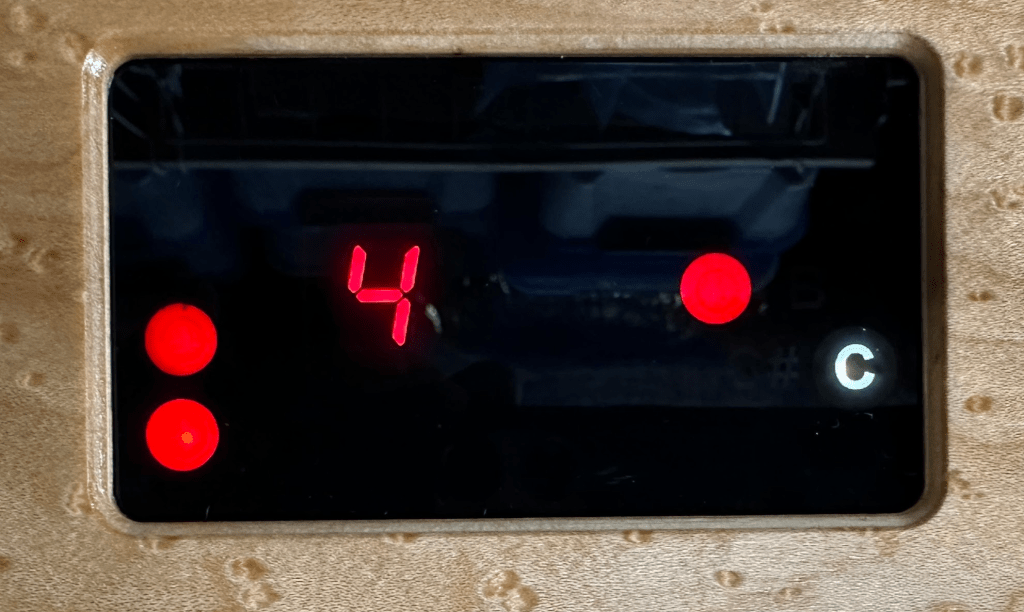
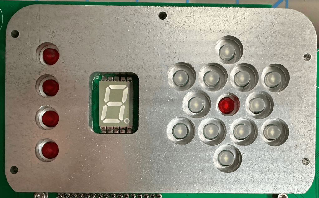
The D-Lev includes a digital tuner that uses a star pattern of discrete LEDs. I wanted the LEDs to show as backlit letters so the specific note could be read. This was accomplished by laser etching 3mm gray smoked acrylic that was masked with black paint. A CNC-cut plastic shroud, painted with aluminum paint to make the inside surfaces reflective, evens out the backlighting and eliminates light bleed between LEDs.
The original D-Lev design outputs SPDIF and TOSLINK digital audio outputs which require an external DAC to generate an analog signal to drive an amp/speaker. In this single-board design, I added two DAC boards and line/headphone amps that output analog signals for the LINE and MONITOR outputs on ¼” phone jacks. The DACs board are harvested from low cost Ali Express DAC modules: https://www.aliexpress.us/item/3256806141175211.html
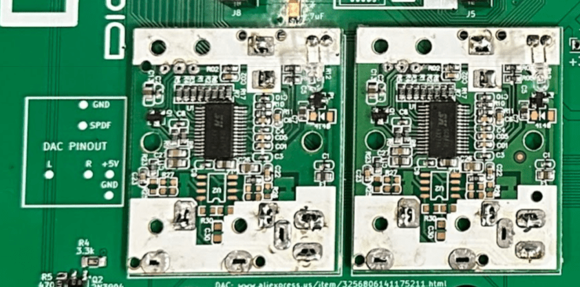
It was cheaper and easier to do this than source ICs and design my own DAC. The DACs then feed two LM4881 headphone/line amplifier ICs. These can either drive an external amplifier or headphones through 1/4″ phone jacks on the front panel.
The digital heart of the D-Lev is an Altera FPGA on a daughter board purchased from Waveshare. https://www.waveshare.com/coreep4ce6.htm

Coils that resonate with the pitch and volume antenna capacitance generate the control waveforms. Unfortunately these coils can’t be sourced from typical parts vendors and must be hand wound. Following the D-Lev guidelines, the coils are wound on sections of 1.5″ O.D. plastic drain pipe. I used this ABS sink drain extension pipe from Home Depot: https://www.homedepot.com/p/Oatey-1-1-2-in-x-12-in-Black-ABS-Sink-Drain-Extension-Tube-HDC9793/316621997 cut into 125mm lengths. The coils are wound with magnet wire tightly spaced in a single layer. The spec are as follows:
- 1mH coil – #30 wire wound over a 71mm length
- 2mH coil – #32 wire would over a 105mm length
I drilled mounting holes and small holes for the wire ends before winding. Eric has videos showing how to wind coils by hand, but since I have a lathe, I used it to partially automate the process by setting the carriage feed to match wire diameter.

After winding. I coated the coils by dripping polyurethane varnish over the rotating coil, at just a few RPM, and let it run over night. Keeping the coil moving lets any air bubbles in the polyurethane disperse and evens out the coating. I put on three coats, which might not have been necessary.
Solder terminals mounted inside the coil make sure the fine wire is not stressed. From there they connect to screw lugs positioned over the mounting holes so that the mounting screws also provide electrical connections.

After software is loaded, each oscillator requires an adjustment for the waveform amplitude at the P_C_DIV and the V_C_DIV nodes. The D-Lev instructions say to adjust the capacitance in series with the coil (C14 and C15 on this board) so that the amplitudes at P_C_DIV and V_C_DIV are between 2 and 3Vpp. This will require an oscilloscope. Also, the adjustment must be done with the same antennas installed that will be used when playing. A convenient way to perform this trim is tightly twist a few inches of wire together and solder it to C14 and C15. Then measure the C_DIV voltage with an oscilloscope and trims offs bits of the twisted wire until the amplitude is 2.5Vpp. Shut off the D-Lev while you are cutting the wire. I’ve found that too high an amplitude is worse than too low as it can put “wrinkles” in the pitch response, so don’t worry if you are at 2.0V.

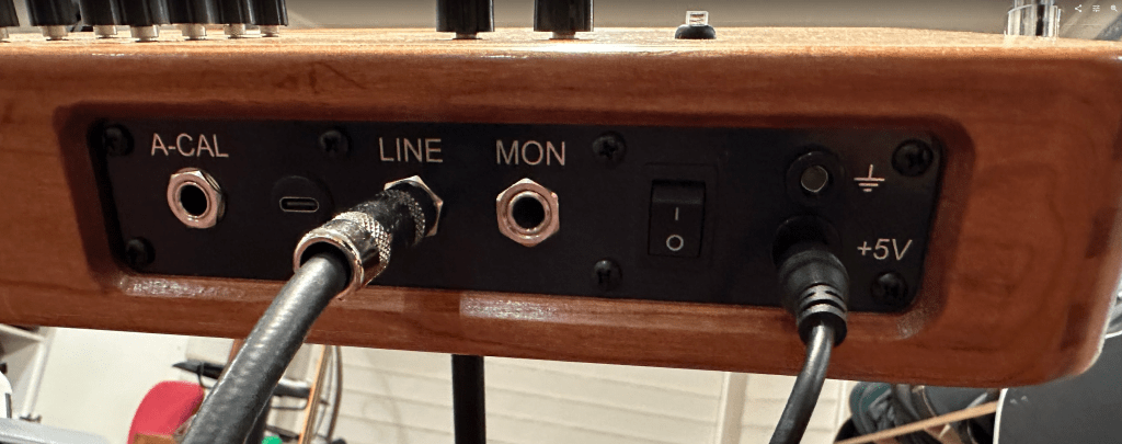
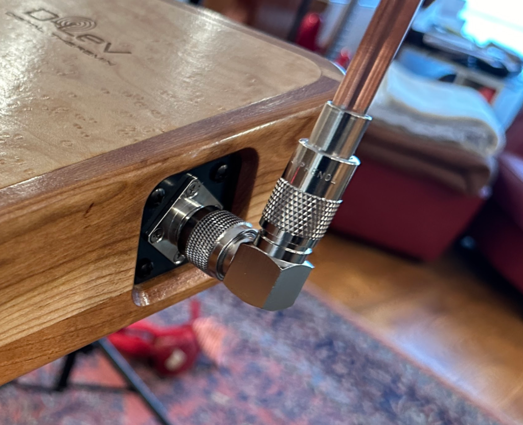
The antennas are 3/8″ copper tubing soldered to UHF connectors. The volume antenna is formed from soft copper tubing that comes in a roll, while the pitch antenna is a section of straight copper tube. UHF connectors are well suited because they don’t move when tightened, and have teeth that allow them to be locked in at 22.5 degree increments so antenna orientation can be adjusted independent of D-Lev case position.

The volume antenna loop was bent with the aid of a spring tube bending guide. This is a spring that slides snuggly over the tubing to keep it from kinking while bending. https://www.amazon.com/gp/product/B00HNQRGME
I was uncertain about mounting the UHF connectors directly to wood, worrying that the water content of the wood might impact the antenna operation, so I designed small PCB panels that insulate the antenna sockets from the wood sides. The front panel is also a PCB. These were very robust, and cheaper/easier to make as circuit boards sans circuitry, compared to cutting them from some other material.
All in all this “art-project” D-Lev turned out quite well. Of course it took much longer than expected, but I’m slowly learning that is what happens when the result needs to be a real finished item, and not a jumble of wires 🙂

Really gorgeous Len! I hope your wife enjoys playing it!
LikeLike