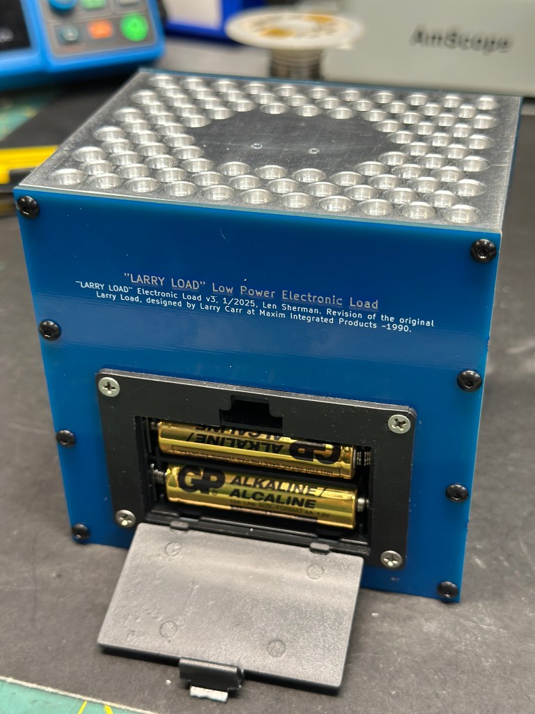
This simple electronic load for testing power supply circuits was a popular lab-built piece of test gear at Maxim Integrated Products. It was known as the “Larry Load” by the lab rats at Maxim because it was designed by an applications engineer named Larry Carr. Commercial electronic loads were available from companies like Kikusui, but those were not cheap (and Maxim famously *was* back then) and Larry Loads were unique in their simplicity, wide range, and every-day utility. Even today, I’m unsure if a commercial load instrument can dial in a load of 10uA. After retiring from Maxim. I had always intended to build a few of these for home lab use. I finally got around to it.
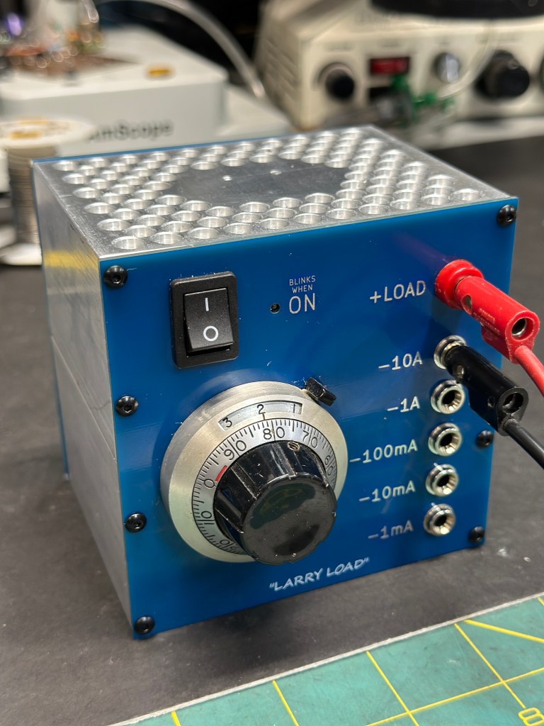
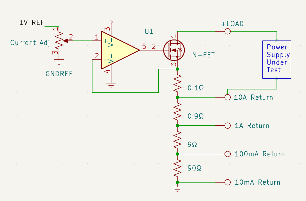
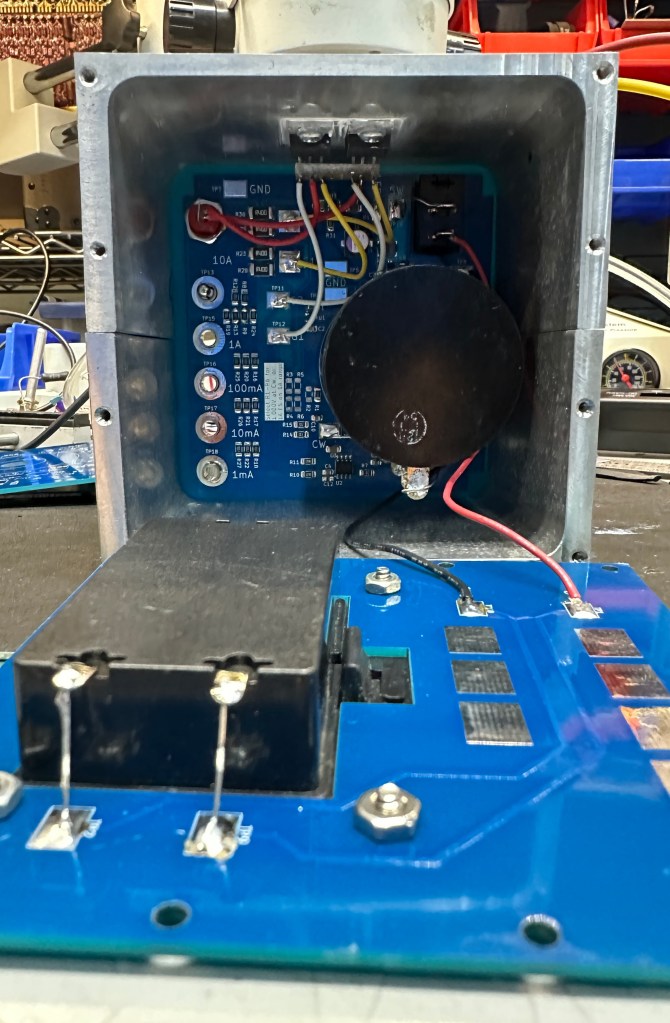
A unique feature of Larry’s design is the absence of a selector switch, despite covering current ranges from 1mA full scale (with 1uA per dial hashmark) to 10A full-scale. Current is sensed by taps on a decade-stepped ladder. Each tap serves as ground return for the selected range. This works because the entire circuit is battery powered and “floats” on the ground of the power supply under test. The basic idea of the circuit is shown below.
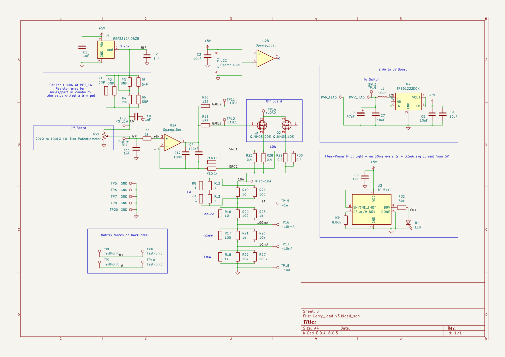
My latest iteration adds a few changes. The original design was powered from a 9V transistor radio battery. Unfortunately 9V batteries are the most costly of any consumer battery in terms of W-hrs/$, and for that reason are my least favorite. A flea-power 5V boost DC-DC converter was added so that the circuit can operate from 2 AA cells.
Even though the original circuit ran on less than 100uA, units in the lab would often be found with a dead battery because users would forget to turn off the power switch. This needed a pilot light, but I didn’t want to consume more current in an LED than did the entire rest of the circuit. By blinking at a low duty cycle (50ms every 3 seconds) with sub-uA timer IC, pilot light battery drain is <7uA.
KiCad files and Gerbers for this design, as well as 3D files for the case, can be found here: https://github.com/lens42/Larry-Load-Electronic-Load/tree/main
This design runs on less than 200uA from 2 AA batteries. Operating current could be reduced, but I ended up using parts at hand, particularly the Bourns 10-turn pot which I happen to have at 30kΩ. If the potentiometer were increased to 100kΩ or more, battery drain could be reduced by about 40uA. Similar “in stock” motivations drove the use of a dual op-amp and wasting half. Even without optimized parts for power consumption, battery life should still be well over 5000 operating hours.
With the selected MOSFETs and heat sinking, loads are limit to less than 50V and something like 20W. The top and bottom of the case are made from 4″ aluminum U channel (again, what I had around) with the top section, where the FETs are mounted, doubling as the heat sink. I drilled a series of pockets in the top in an attempt to get more radiating surface. The top will still get pretty hot at 20W. Different FETs could be substituted to increase the load voltage rating and more elaborate heat sinking would extend the power. A nice feature of a floating electronic load is that you can always parallel two (or more) to increase power if needed. On the inside of the top case, FETs are mounted with insulators to isolate the drains, otherwise the case would be at the same potential as the positive input terminal (not recommended).
In order to avoid needing a trim pot, a network of resistors between the reference output and the 10-turn pot sets the divider ratio. The network (R1-R6) is mostly unpopulated but allows a flexible arrangement of series/parallel resistors to dial in the divider ratio to get exactly 1.000V on the pot.
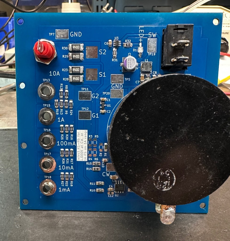
One other self-imposed twist in this design is that I wanted the circuit PCB and the box front panel to be one and the same to simplify construction. That meant sticking to a surface mount design with no vias and a layout that would effectively be single-sided. Since the circuit is not complex, this wasn’t too hard to achieve. I used mostly 1206 passives because I had room, my eyes are old, and I could run a trace under a part if needed, though it turns out that wasn’t necessary.
The simplicity of this design comes at the cost of some limitations: namely no programmability, no data logging, and no transient test ability, but if all you want is a simple way to dial in a load, this is hard to beat.
Other details
For anyone making boards with the KiCad files, below are links to the battery holder (AliExpress): https://www.aliexpress.us/item/3256805864540191.html and the rocker switch (Amazon): https://www.amazon.com/gp/product/B0B6ZVJZDZ which fit cutouts in the PCB.
I used a 10-turn Bourns potentiometer and large Beckman Duodial turns-counting dial from my stash. Getting similar stuff from Digikey or Mouser is unfortunately expensive (roughly $20 each for the pot and dial). The large Duodials are likely out of production, but can still be found on eBay and surplus outlets. $40 for pot and knob hardware probably points to an encoder and digital pot being a more sensible solution, but since I’m an old analog guy, I’ll leave that design to the “new kids”.
A Bit About Larry Carr
While working on the front lines of the portable power “boom” (ha ha) in analog semiconductors, I was fortunate to work with some very smart people. Larry Carr was one such person who, prior to Joining Maxim, spent a few decades designing all sorts of hardware in the industrial world. I hired him into the applications group at Maxim some time in the late 80s or early 90s (fuzzy memory). Interviewing him was unusual, one, because he was a few decades my senior, and two, because the interview turned into a bit of an argument. He didn’t think he could do an applications engineering job without experience in the innards of semiconductors and the semiconductor business. I was trying to convince him that he would be a secret weapon because he had already spent decades designing equipment WITH ICs and customers would love talking to him (they did). Fortunately, I won the argument. Sadly, Larry passed away several years back. But his unique style and presence in the apps group at Maxim is well remembered.

Dear Sir
I am Roelof and i live in the Netherlands . One of mine hobby,s is electronics. I have read with a lot of plesure your post about the Philips 212 Arduino project. very interesting.
I bought a REV 2 board without any components. I noticed that is different than the REV board 1. can you help me please were to find the schema with the components so that I can place them on the REV 2 board.
Greetings Roelof
LikeLike