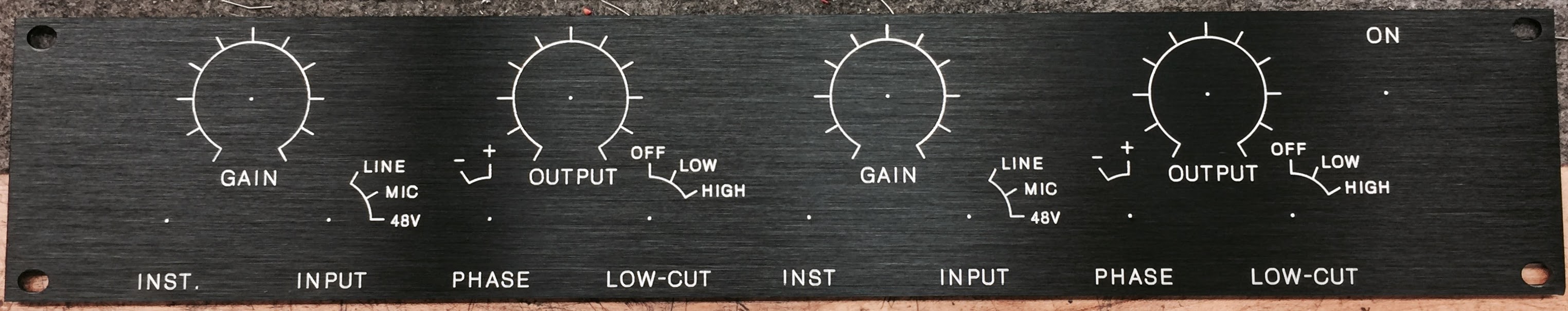
This is a home build of a two-channel tube-based studio preamplifer / direct box. The project web site is here:
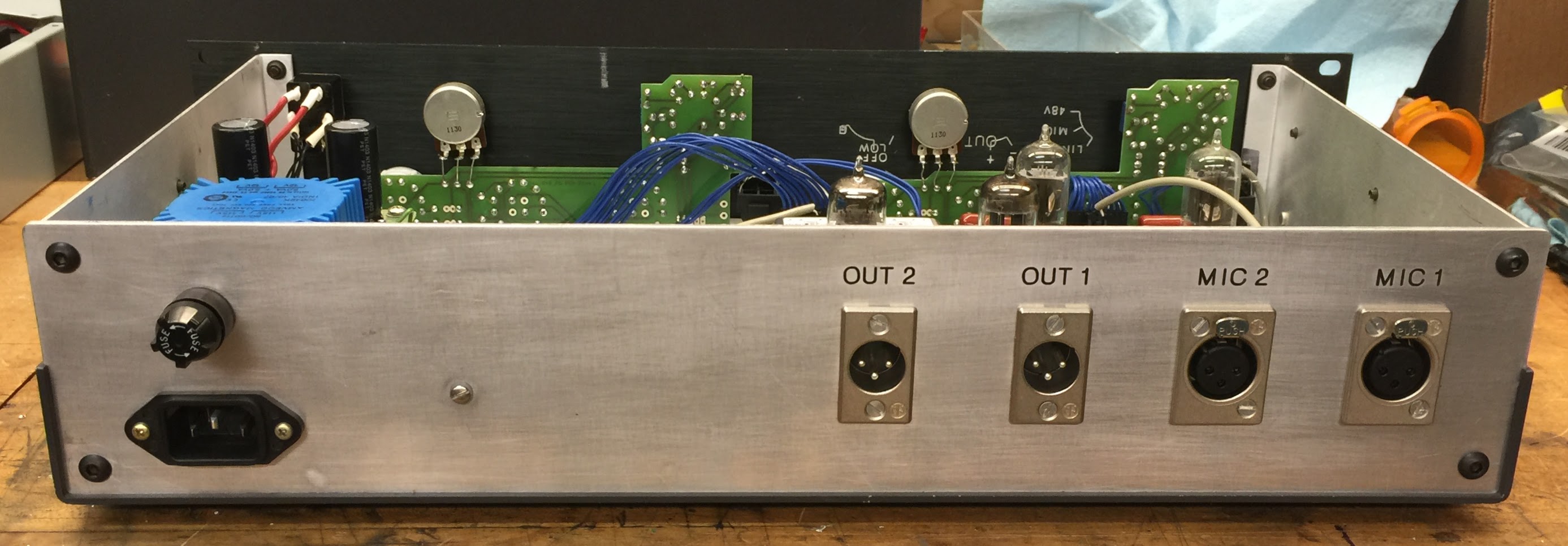
There are several recommendations/changes I have for future G9 builds, but it will take some time to get it all posted. Here’s an interior shot of my completed preamp.

One change I made to the original design was to the power supply. The original power supply design ran much of the power through two cascaded transformers in order to get an isolated high voltage output without needing a transformer designed specifically for tube circuits. This allowed the use of more common transformers, but at the price of a less efficient design (since the losses of cascaded transformers are multiplied) and extra weight. The original design calls for two 30VA transformers.
The revised supply uses three (still common) 10VA transformers that I was able to get surplus. One transformer powers only tube heaters (12V x 150mA x 4 = 7.2W), while the other two power the 250V plate supply (250V x 20mA max = 5W) and the 48V (48V x 50mA max = 2.4 W) phantom power supply.
Note that these changes were designed with 110VAC mains power in mind.
Here is the original schematic, with none of my edits:
Below is my modified transformer arrangement and power supply schematic:

The connections of the transformers in the revised design may look a bit odd. Each transformer has two 12V 5VA output windings and two 110V input windings. Rather than connect transformers in cascade with one backwards to get a high voltage output, the design takes advantage of the split primaries and uses one primary winding in each of two transformers as secondaries wired in series for the 250V rail. Then 3 of the 12V secondaries are wired in series to bias the 48V regulator. Since the load on 48V is usually quite low (not more than 10 or 20mA) is was not necessary to connect the four available 12V windings in series. All that would have done is generate an overly high unregulated voltage and more heat in the 48V linear regulator circuit.
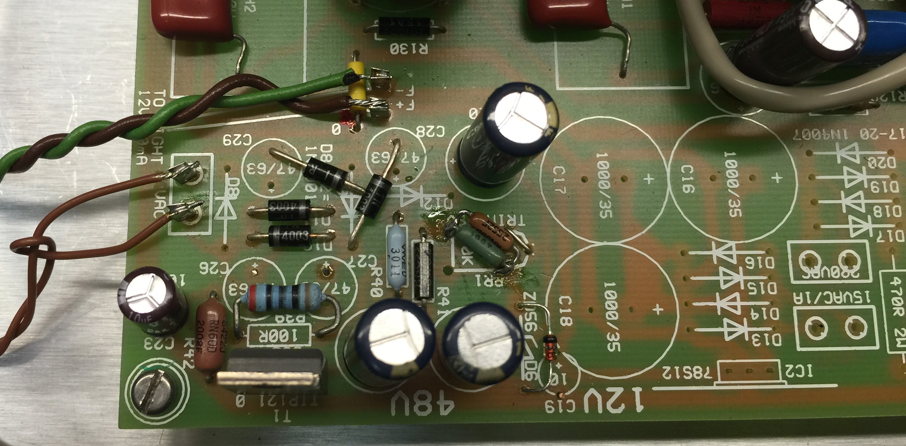
I also modified the high voltage regulator by forgoing the TL783 IC regulator and the zener farm planted around it (for protection I presume), and opted instead for an all-transistor design. Some changes were also made to the 48V regulator since I did not need the diode-capacitor voltage multiplier (D8-D12, and C28-29) anymore.
In the heater supply, I used an LM2940-12 low-dropout regulator rather than a standard 78S12 type. Since my AC input was 12V rather than 15V, I needed the extra 2V of headroom the LM2940 provides.
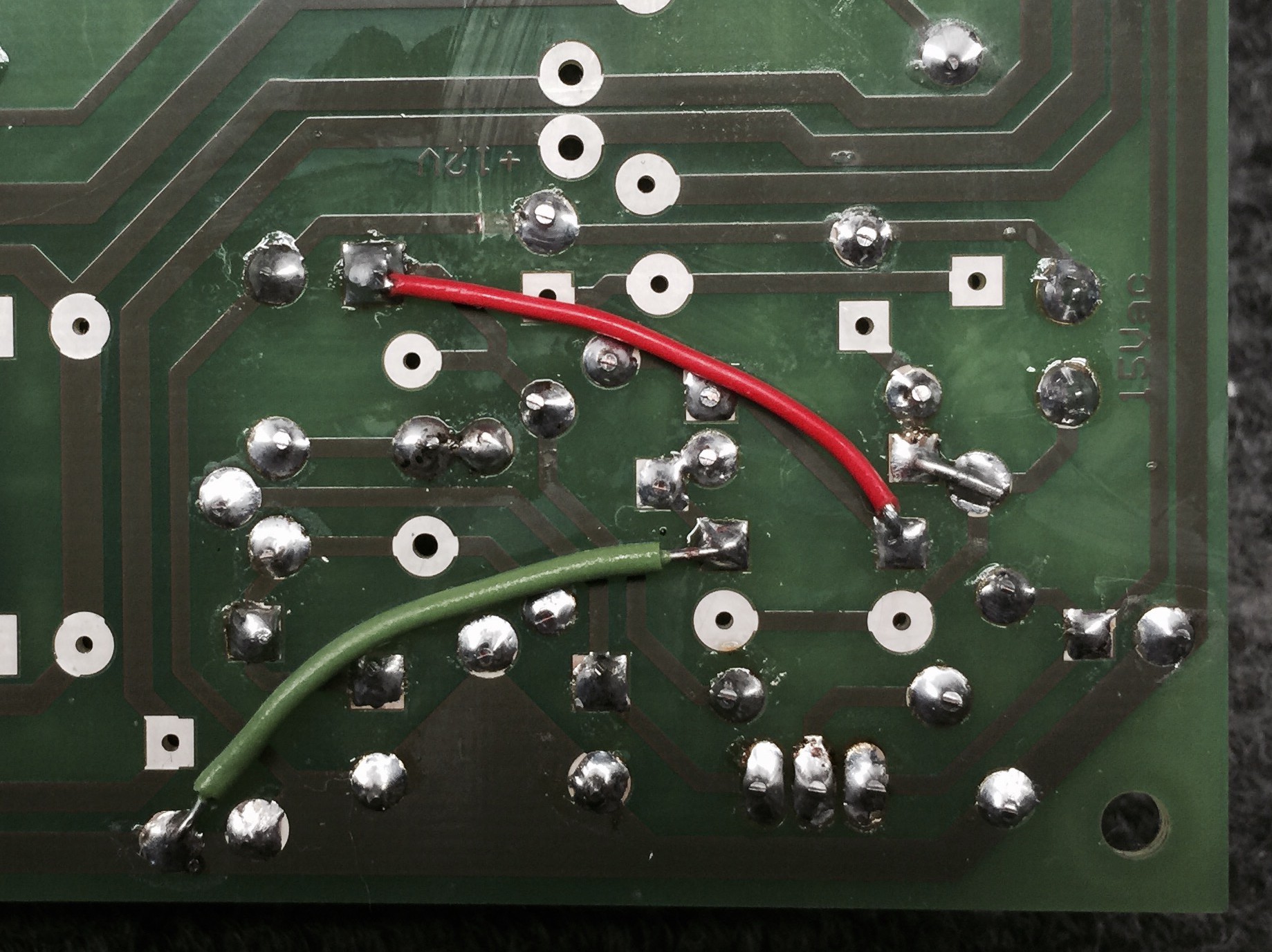
Below are some other pictures of the build: