This is a repair of Bose L1 tower PA system. These skinny tower speakers are somewhat of a marvel because they are designed to stand behind the musician (aimed RIGHT AT the microphone) and don’t generate feedback (in most situations). Ah, the miracles of DSP.
It turns out these PA’s have a frequent failure in their power supply. Read on for details.

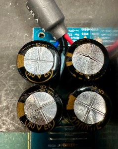
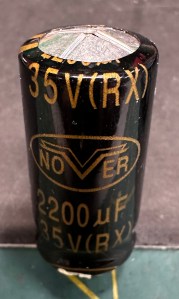
UPDATE 9/16/2024: Another potential problem area for L1s are the 2200uF output filter capacitors (C504,C505,C506,C522) in the +/-27V power supply boards. I have begun to find these cracked open and bulging at the tops. If you see this on any of these capacitors, all of them (8 or 12 depending on the model) should be replaced. Even if you don’t see damage, it might be a good idea to replace them anyway as the parts cost for twelve is only about $20-30. There are also four 470uF output capacitors on the aux supply board (C625,C629,C633 and C636) made by the same manufacturer (“NOVER”) that should probably also be replaced.
I’m not sure I would recommend a wholesale replacement of all electrolytics on all boards, as that would involve a prohibitive amount of cost and time, and I’ve not seen the other caps exhibit the problems these did, but I have to admit that before now, I have not been looking specifically for this issue. Here are Digikey links for suitable replacement caps. They also have less and more expensive parts if you want to go cheaper or better (i.e. 125C rated rather than 105C, higher operating hours, and higher ripple current ratings).
https://www.digikey.com/en/products/detail/panasonic-electronic-components/EEU-FR1V222B/2504161
Also a link for the aux supply caps:
https://www.digikey.com/en/products/detail/panasonic-electronic-components/EEU-FC1V102/266314
UPDATE 2/13/2024: For those who want to crack open their dead L1, can do basic soldering, but struggle with troubleshooting electronics, or don’t have test equipment. Here is a list of parts I’ve replaced and their Digikey part numbers. Most repairs don’t involved all of these (usually only two or three), but since the parts are not that expensive, you could shotgun all of them and stand a decent chance of getting an aux power board back up.
- D605, D606, D607, D608, D609: Digikey part # 497-3216-1-ND
- C610: Digikey part # 493-13294-1-ND
- Z601: Digikey part # BZX55C18-TRGICT-ND
- D601: Digikey part # UF4006CT-ND
- R614: Digikey part # CF14JT22R0CT-ND
- R621: Digikey part # A138094CT-ND
- R620: Digikey part # CF14JT1K20CT-ND
- Q601: Digikey part # 497-STFU10NK60Z-ND
(Note that in the comments I messed up the part number for Z601. It’s correct in the above list)
UPDATE 10/22/2021: Since I first published this, I’ve gotten a lot of inquiries from people regarding repairing their L1s. For people local to northern CA, I’ve swapped working units for their bad ones plus cash. Then I try to fix the dead one I took in trade. All together now I’ve worked on five units and succeeded fixing all of them. I’ve also successfully repaired an aux supply board that someone extracted from their L1 and sent to me (Unit 3 below). For those trying repairs at home, here are my results (I’ll try to update as I see more units):
6 of 7 failures have been in the “Auxiliary Power Supply Board” (read below for more details). I recommend starting trouble shooting there if you L1 does not power up but please note the dangers of troubleshooting circuits that are hot to the AC line (noted elsewhere in this post).
Unit 1: My first attempted repair which started this blog post – D608 open – REPAIRED
Unit 2: D601 and D608 bad – REPAIRED
Unit 3: D601 bad – REPAIRED
Unit 4: D609 bad but also Transformer T601 open between pins 6 and 8. I was lucky in finding a broken wire that was accessible outside the windings. I reconnected the wire with some very carefully soldering. – REPAIRED
Unit 5: Had a working Aux Supply, but no sound from one half of the tower. The +/-27 power supply (there are three) for that channel power amp had smoked MOSFETs and other components. I harvested a +/-27V module from Unit 4 to get this one out the door, then repaired the supply by replacing two MOSFETs, two zeners, several resistors, and one rectifier.
Unit 6: A bit of a train wreck with many visibly charred components. I ultimately had to replace D606, D602, D614, Q601, R614, R620, R621, SCR601, TH603 and Z601. Whew! But now back from the dead. – REPAIRED
Unit 7: replaced D602 and D607 – REPAIRED
Tally so far on L1 repair is 7 for 7!
Back to the original blog post:
The tower speakers slide into the base where they are both supported and electrically connected to the amplifier. All the circuitry is in the base.
The bad news is if you have a problem with this first generation L1 (ours is about 10 years old), Bose is zero help. They will no longer repair them and only implore you to get a new system. To make matters worse they are completely uncooperative about supplying schematics (though I was able to find documentation on-line).
Our L1 suffered a power supply failure, which is apparently fairly common as these units age. The culprit is the “Aux Power Supply” shown in the block diagram at this link.
The below linked doc has schematics and instructions for disassembly. Even though it provides guidance, I still recommend taking LOTs of pictures. Especially of where connectors plug in.
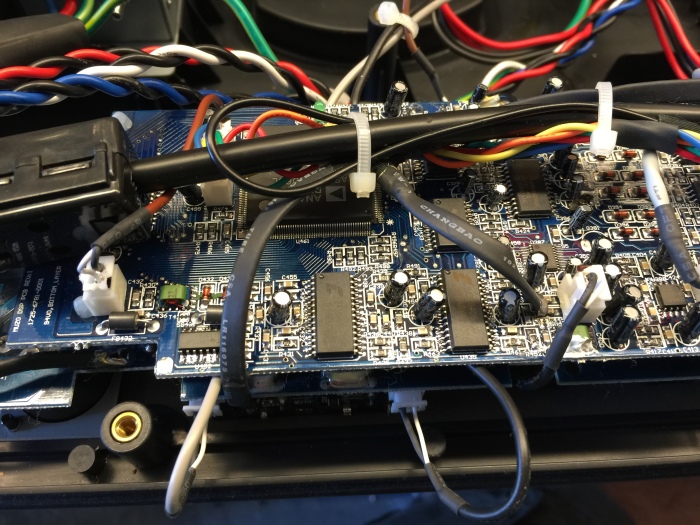
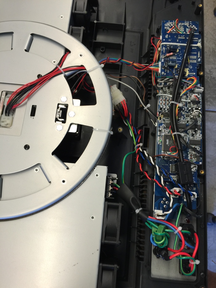
Dissembling the base is no small task. There are screws everywhere, and you have to pull almost everything apart to get at anything useful. Below shows the top cover and control panel PCB after unplugging from the power chassis.
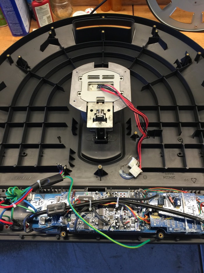
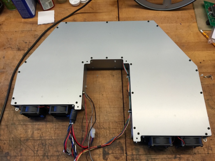
Pull the U-shaped top cover and you are in.
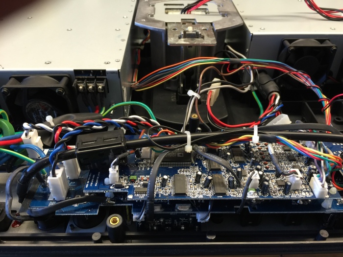
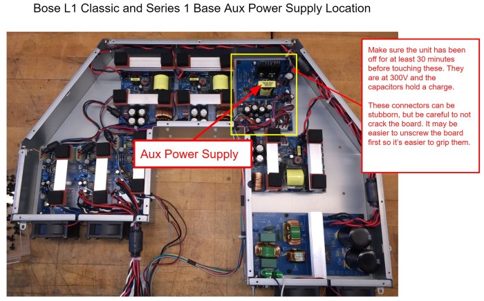 I pulled out the Aux Power Supply board (upper right corner) and the EMI filter board (lower right corner) in order to troubleshoot the power supply on the bench.
HUGE WARNING! The EMI filter board and large parts of the Aux power supply are NOT isolated from the AC line! I powered this from an isolation transformer before hooking an oscilloscope. Make sure you fully understand what this means before proceeding with any testing. Unisolated circuits are VERY dangerous to work on.
Warning #2! The output of the EMI board is about 330V and the big capacitors on that board can store that voltage for up to 30 minutes time after the base is unplugged. Check that the voltage has fallen to a safe level (<20V) before touching anything or removing any boards.

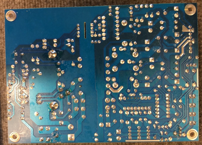
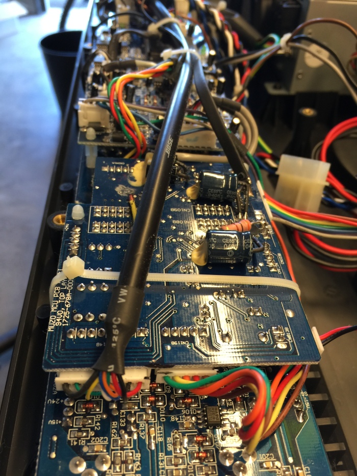
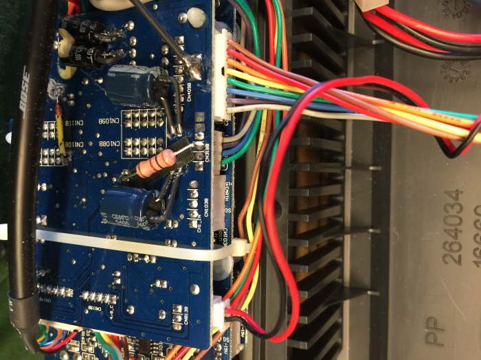
Aux power supply board
I found some unrectified AC waveforms in places that should have been DC, and pinpointed the problem to a large rectifier diode that was open-circuit. After replacing this diode, all the Aux rails powered up, but many voltages were off (by 5V or more) from the spec’d values. I spent several days chasing this with no progress, until I guessed that the amplifier and the rest of the L1 circuitry might need to be connected to the Aux rails before they would read the correct voltages. This turned out to be correct. When I assembled and temporarily wired everything together, the Aux voltages read correctly. These rails are not tightly regulated and needed the load of the circuitry to pull them to their proper voltages.
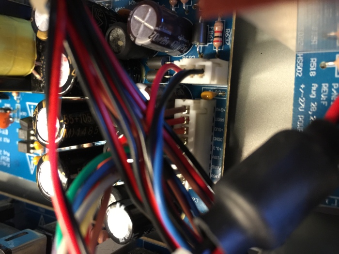
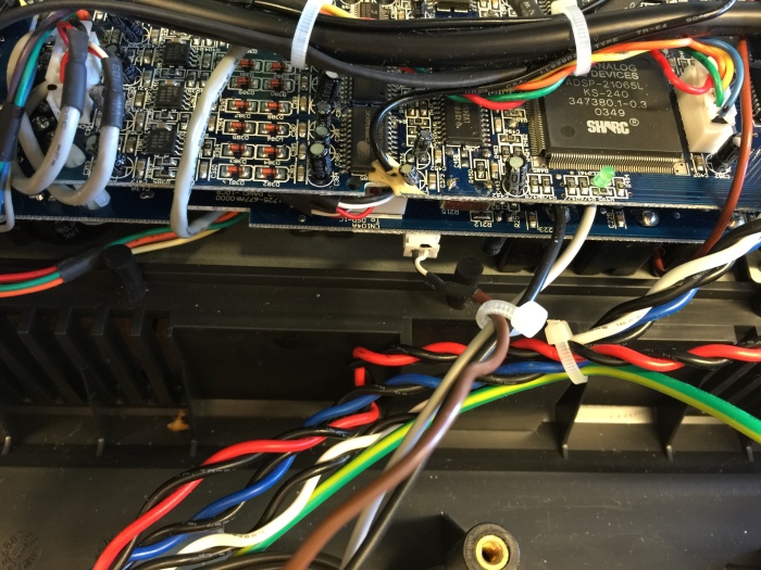
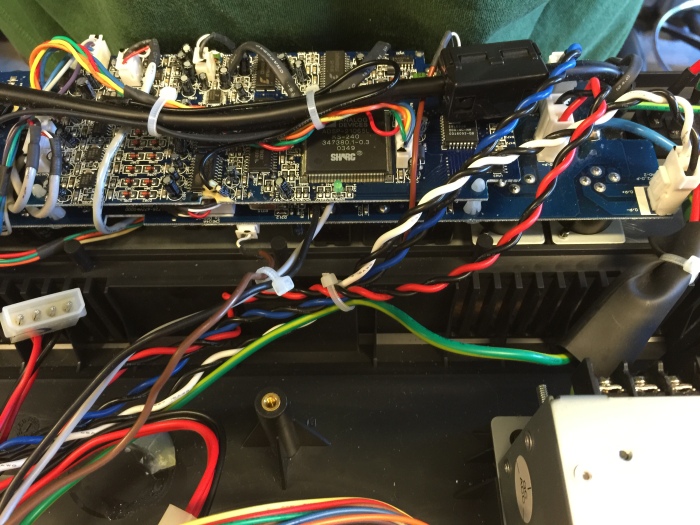
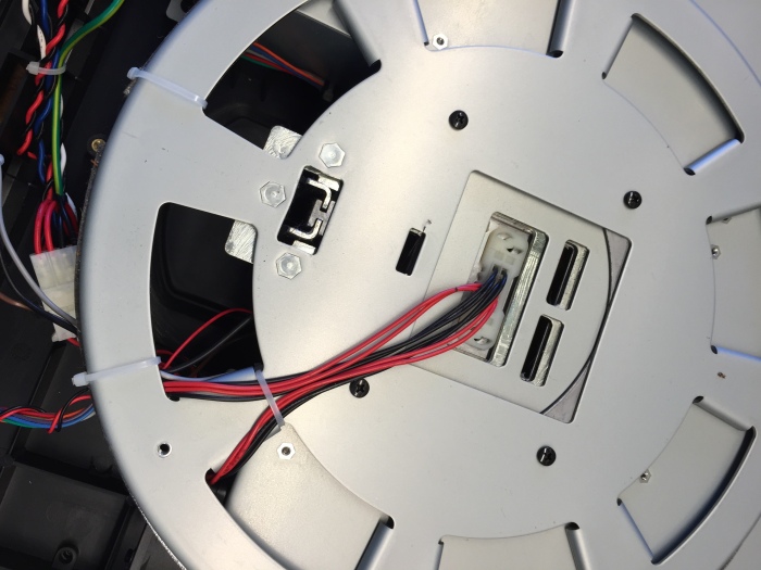
Other miscellaneous inside images below, mostly to remind me where all the connectors go:


I have read your posts and would like to know if this applies to the Bose L2 Tower PA? I have two of the above mentioned systems and have seen both units go out. Can you tell me if the capacitors and other parts you’ve mentioned in your posts would be the same for the L2 system?
LikeLike
Hi Bill – I don’t know of a Bose L2. Did you mean Bose L1 Model II? If that’s what you have, the circuitry is very different from the L1 Classic and Model I. I tried, unsuccessfully, to fix an L1 Model II, and ended up sending it back to Bose for repair. At that time (quite a few year ago) they still offered service on them for a flat $250, but I don’t know if that’s still the case. You can ID your system with the info at this link: https://toonz.ca/bose/wiki/index.php?title=Different_Models
LikeLike
Thank you for your response to my questions. And you are right, I do own the Bose L1 Model II. I was hoping the two Bose systems were similar, but unfortunately they are not. I am looking for repair options through a certified Bose repair center near my location so we’ll see what happens. Again thank you for your response and knowledge regarding my concerns.
LikeLike
Hi, and thank you so much for this extensive guide! I’ve tried shot gunning all the components on an aux power supply to no avail. And then I saw the additions where you mention 2200uF output filter capacitors, and also the ”four 470uF output capacitors on the aux supply board (C625,C629,C633 and C636)”.
However, the two links for suitable replacements go to the 2200uF capacitors – would you mind linking to a suitable replacement for the 470uF caps?
LikeLike
Here’s a link https://www.digikey.com/en/products/detail/panasonic-electronic-components/EEU-FC1V102/266314 and I’ve also added it to the post. I’ve never actually seen the aux caps be the cause of failure. I only mentioned it because they are the same brand to fail on the +/-27V board. I will contact you.
LikeLike
Thank you so much for the guide. I have been able to fix one unit and it is working beautiful. I have a second unit that I replaced all the usual bad components and it works, but it has two problems. It has a red power light after about a minute or two. And a slight hiss. the hiss appears to be from the input board, when I unplug one channel it goes away. Any suggestions would be great. Not sure how to test why the MCU is turning the power light red. Thanks again for your help.
LikeLike
buenas tardes, podrían apoyarme. Conseguí un Bose L1 modelo 1S extender. Le falla la perilla de volumen, por lo que se nota anteriormente y se había cambiado, alguien tiene información de cual es la que debe llevar algún modelo en específico? Les agradecería sus comentarios. Saludos
LikeLike
Hi, need help with an L1. In the East Bay. Would you take a look?
LikeLike
Hi Lens, I need your valuable help. I had an L1 that was dead due to a problem with the auxiliary power supply. Now it has been repaired with the faulty diodes and MOSFETs, I have all the correct output voltages, the unit powers on but is silent. It seems to be in protection mode (I measure 5 volts on the pin). Everything seems to work, the inputs blink with the signal, etc., but it is completely silent.
Do you have any suggestions for me?
LikeLiked by 1 person
I sent you an email.
LikeLike