
MC275 (i.e. MC217)
I’m a fan of old McIntosh HiFi equipment, especially their tube power amplifiers. They have a very unique design both electronically and also physically. For those unfamiliar, below is one of their flagship amps of the 1960s, an MC275, which outputs 75 Watts per channel…..and weighs close to 70 pounds!

I’ve had, for several years, a partial collection of parts (transformers, tubes, etc) to build a copy of a much more modest stereo amp called the Dynaco ST35. Dynaco was a lower cost competitor of McIntosh in those days but was still considered a good quality path to HiFi for many budget conscious college students (like me). As you can see below, the Dynaco unit, true to its budget genealogy, is a pretty plain box.

I wanted to make use of my tube amp parts, but in a way that “looked cooler”. I decided to build a “Mini-me” of a McIntosh MC275 with the innards of a Dynaco ST35. The key to this would be the metal work. Two tricky aspects in particular were the McIntosh slanted front panel and the transformer covers.
The sheet metal design features in Autodesk Fusion 360 CAD software were a great help. I figured I had no chance of success unless I modeled almost everything and made sure it all fit (Even with modeling, I still hit some snags that I’ll detail later). The plan was to design a sheet metal chassis in Fusion 360 and have it laser cut and folded by OSHCut. If I modeled carefully, I should be able to get ALL the holes laser cut so no manual drilling or cutting would be needed. This became especially important when I realized that the only way I could copy the mirrored look of the MX275 was to use stainless steel and polish it, since chrome plating was not an option, and stainless is harder to drill or cut in a home shop than steel or aluminum.
Mechanical Design
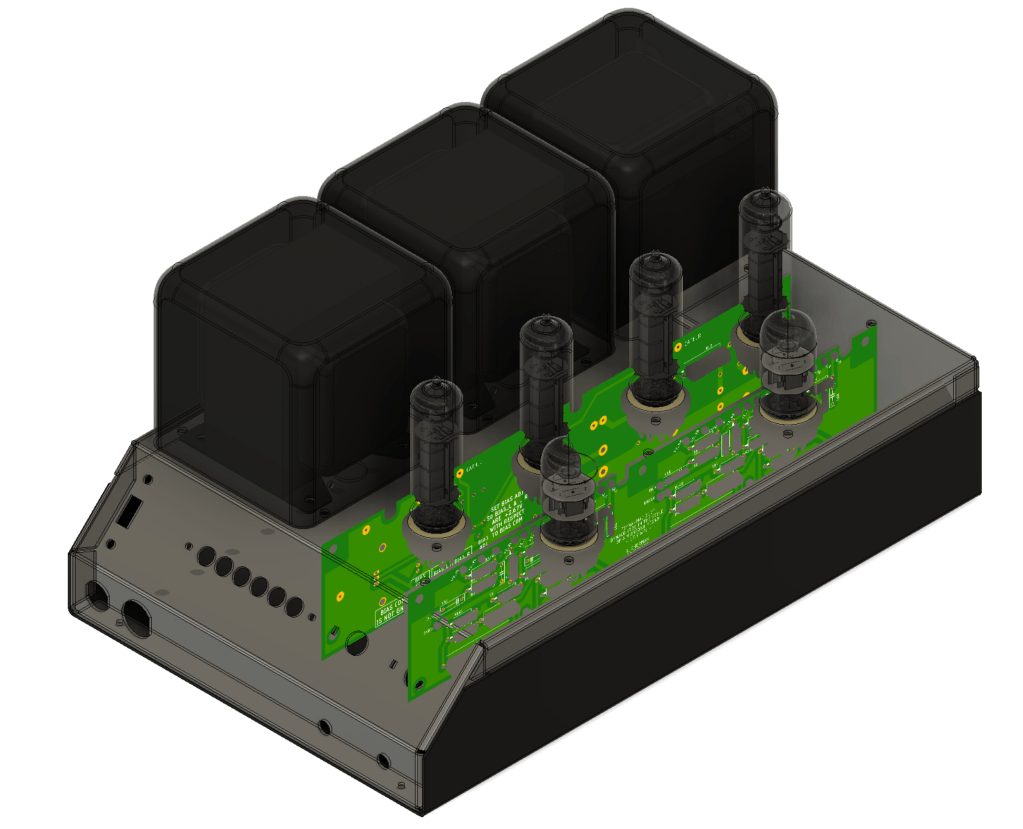
I created as complete a 3D model as I could. This included chassis metal, transformers, tube sockets, tubes, brackets, etc., as well as printed circuit boards imported from Autodesk Eagle. Some part models could be found online from sites like Grabcad, while others had to be created. There were months of playing with positions and nudging parts around before I settled on final positions.
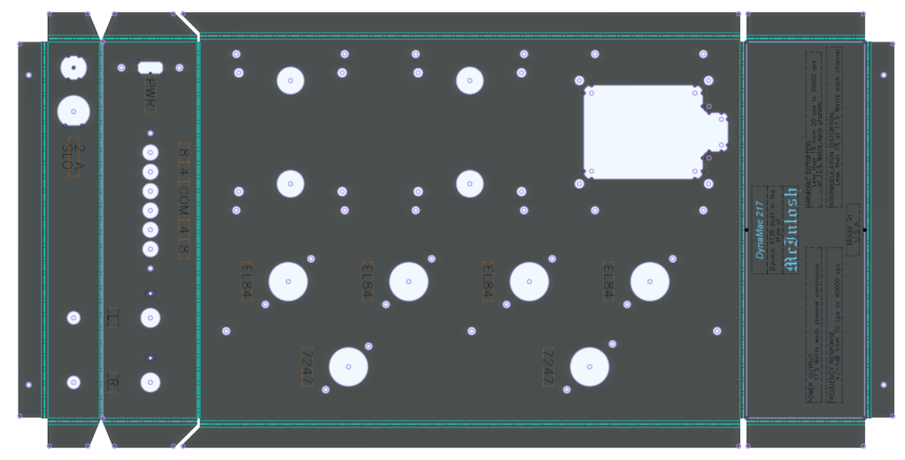
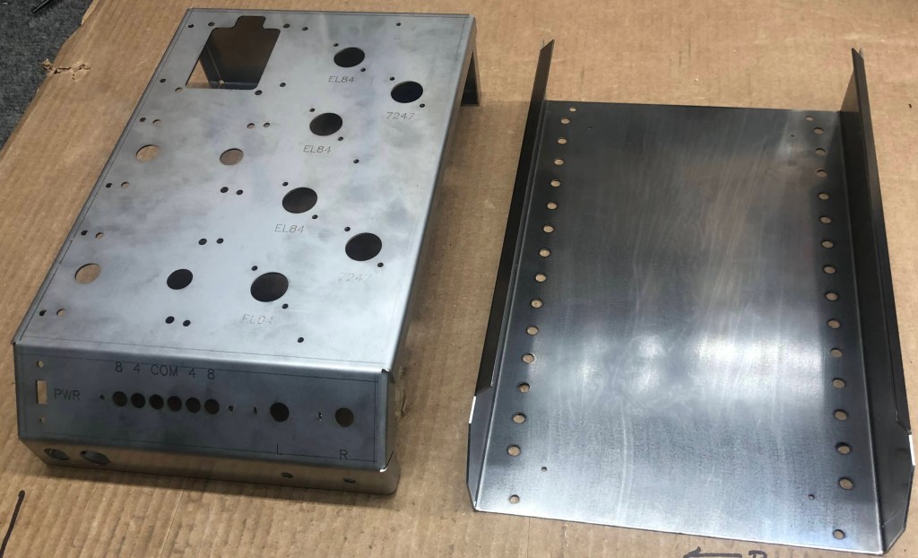
The top chassis pre-fold layout is shown below. Fusion 360 generates this “flat pattern” with bend lines which is then exported as a dxf for OSHCut. The lettering in the below pattern was added with hope that OSHCut’s laser could etch as well as cut. It sort of can, but the result on stainless did not show up as dark lettering, but as fairly faint lines which were made more faint during my hand polishing. For etching, OSHCut uses the same laser as for cutting, but at lower power. It would have been great to have the panel fiber-laser marked before bending, which would have given me nice dark permanent letters, but alas, I found no vendors that offered this.
The bottom cover was much simpler than the top, and made from 18 gauge plain steel, not stainless, since it would be painted black anyway. The top and bottom cost a total of about $200, clearly not cheap, but no more than any other means that had a decent chance of achieving the same result.
The transformer covers could have been a problem because I did not think I could fabricate them and get the nice rounded corners that the MC275 transformers have. Luckily I *did* find covers that had appropriate dimensions from a Chinese seller on eBay.
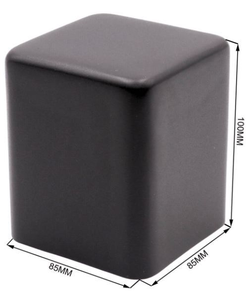
Here’s the eBay link, but who knows how long this will be valid: https://www.ebay.com/itm/191344804799
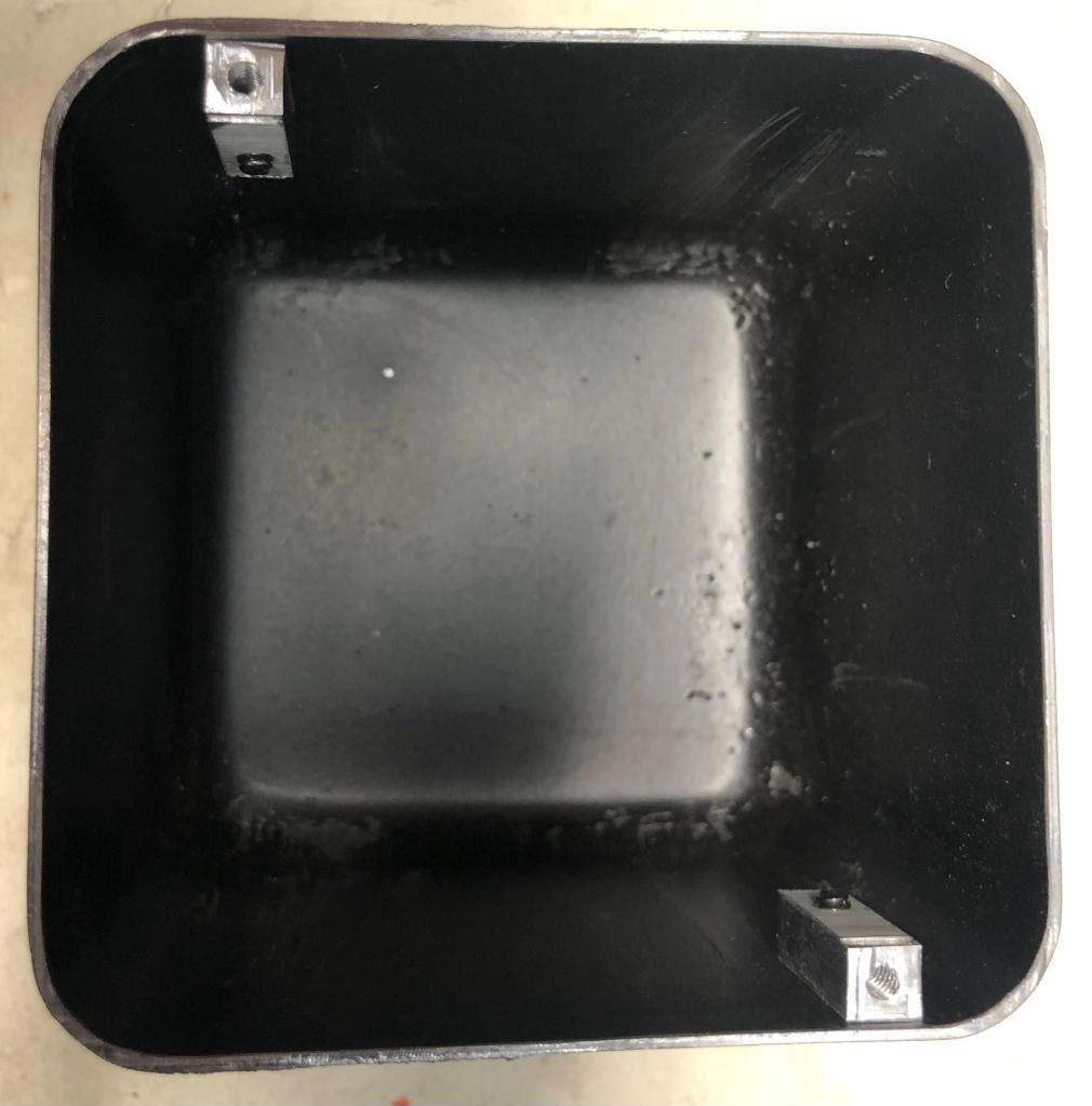
The cans were taller than I wanted, but I was able to cleanly cut them down from 100mm to 80mm. This meant cutting off the mounting brackets on the bottom edge, so I had to make new mounting studs that would bolt to the cover as well as the chassis.
The Circuit
As mentioned, the circuit was from a Dynaco ST35 using reproduction transformers from Dynakit Parts https://www.dynakitparts.com/shop/st-35-transformer-set/
I got these a few years ago for about $200, but now the price is higher ($300) and they have no stock.
The ST35 (and other Dynaco amp) manuals are hosted at Dynakit Parts: https://www.dynakitparts.com/manuals/
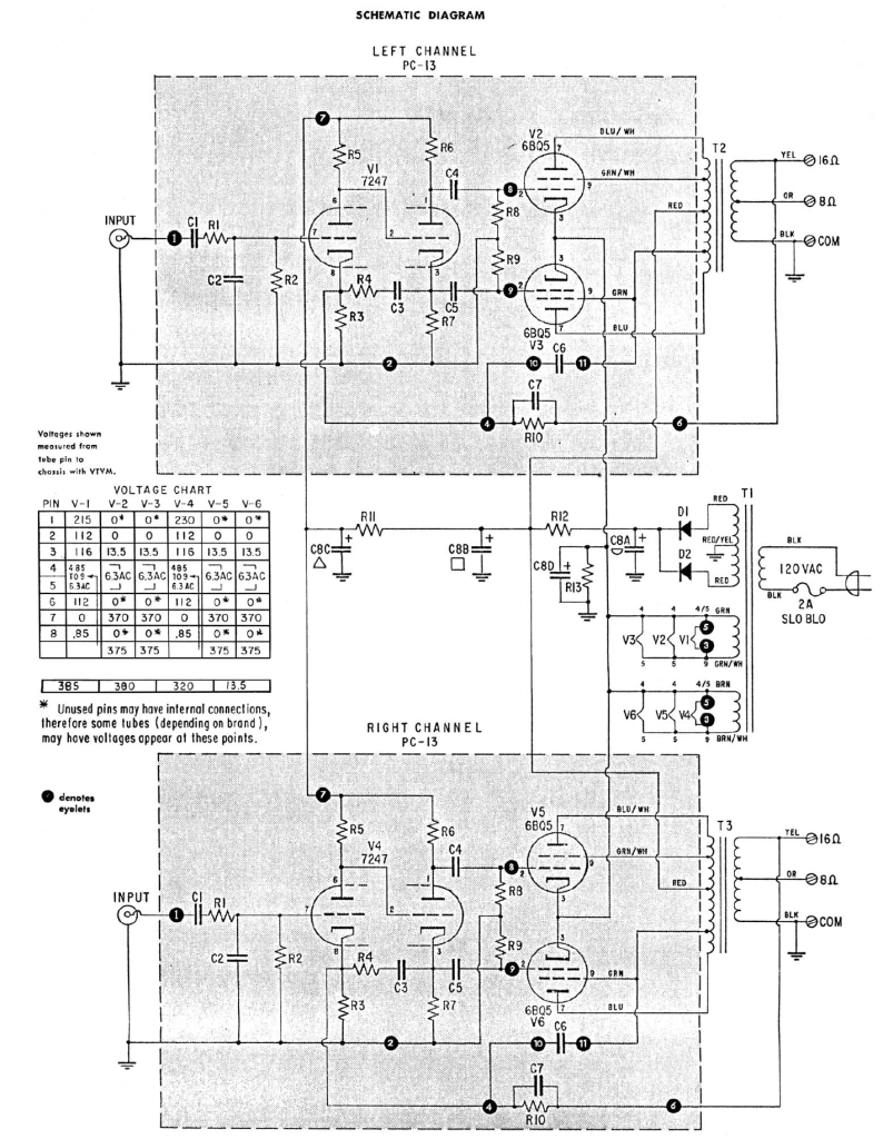
The original ST35 schematic:
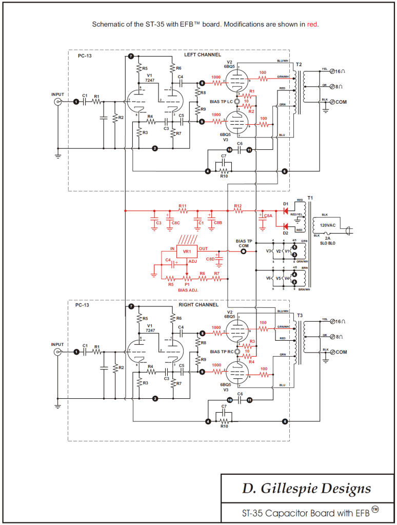
In addition to the basic ST35 circuit, I implemented an upgrade known as “Enhanced Fixed Bias (EFB)” devised by Dave Gillespie, which is described in detail here: http://www.tronola.com/A_New_Look_At_An_Old_Friend.pdf
I also added input volume controls to each channel to match the McIntosh design and functionality, and a power switch, which neither the Dynaco or McIntosh amps had.
The Gillespie modified schematic with EFB (but does not show my added input volume pots):
This and other enhancements for Dynaco amplifiers can be purchased from Dave here. There is also more EFB documentation at this location: http://tronola.com/html/daves_store.html
Besides the EFB mod, I made one other change to the Dynaco circuit to accommodate the Dynakit Parts output transformers. Since these had 8 Ohm and 4 Ohm taps, rather than 16 Ohm and 8 Ohm, the feedback resistor, R10, which taps the 16 Ohm output on the original circuit, needed to be changed since the feedback voltage from the 8 Ohm output would be lower. R10 was changed from 27k to 19.6k to accommodate the lower feedback signal.
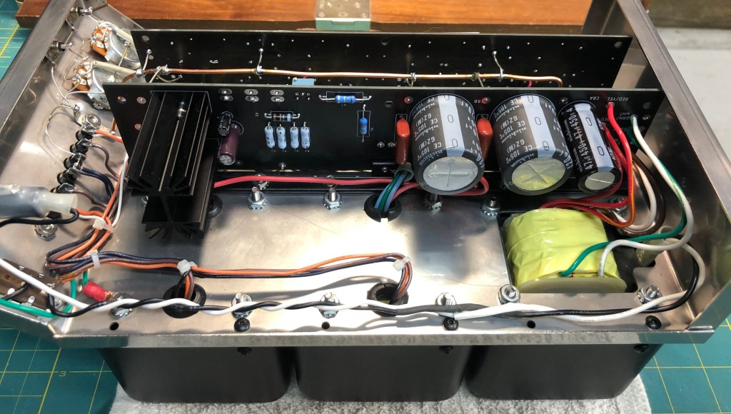
Since I was creating an entirely new chassis and layout for the SC35, I designed printed circuit boards (PCBs). I considered wiring the amp with a turret board, which would have been closer in spirit to the original McIntosh construction, but ultimately chose PCBs because the power supply and EFB modification uses a TO220 IC package and heat sink which would look awkward with turret board wiring. So if the power board was to be a PCB, then the rest of the amp might as well be also.
Construction Photos
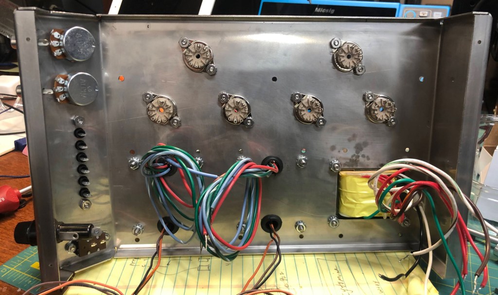
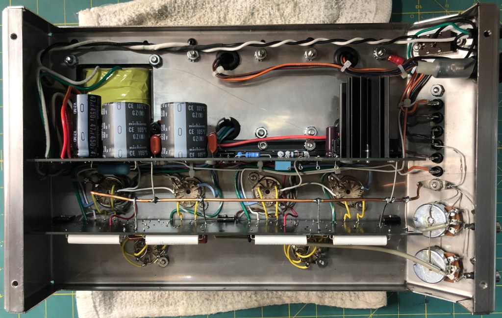
Below is a shot of the chassis inside before wiring. I should note that there were a lot of iterations of tube socket rotation angles in CAD and on paper to minimize the wire runs between the tubes and PCB and keep the input signal paths as short as possible.
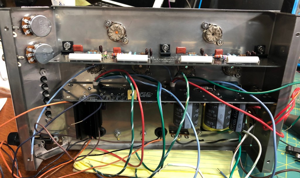
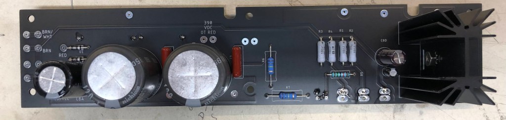
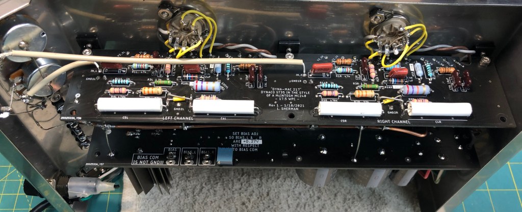
The below picture shows the amp PCB. Eagle eyed viewers will notice the “X” pattern jumper wires between the large white capacitors. It turns out that when you connect the coupling caps to the wrong output tubes you end up making a 17 Watt power flip-flop! Ooops. At this point I thought about ordering new boards, but perfection is the enemy of the good, and I was too close to the finish line.
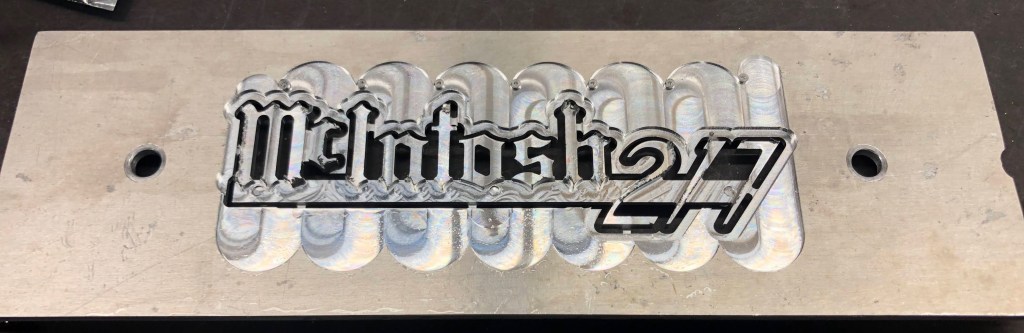
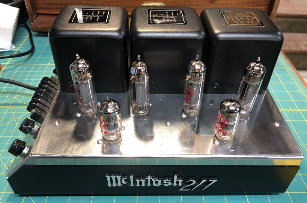
The “cherry on top” for this build was a CNC’d copy of a McIntosh badge. Putting a McIntosh label on this project is admittedly a total lie, but I couldn’t resist. Of course McIntosh never made a 217 (two times 17.5 Watts per channel), but I did! ….sort of.
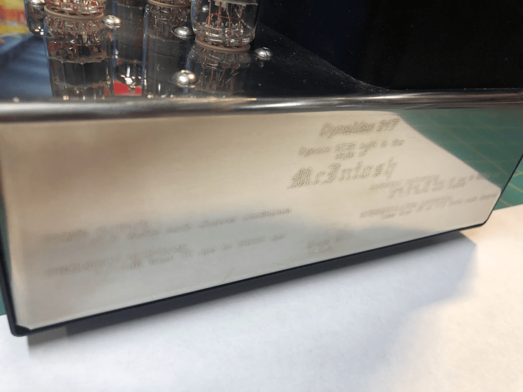
As shown below, I also tried to mimic the McIntosh rear lettering with laser etching. Results were not great, but someone who looks closely can just make out the text. It says, “DynaMac 217, Dynaco ST35 built in the style of McIntosh”. Below that are the Dynaco ST35 specs from their documentation, printed in the same locations that the McIntosh specs would be.
All in all, this amp turned out quite nicely. It is stone quiet with respect to hiss and hum so I guess my PCB layout and grounding schemes were good. I spent a lot of time in layout minimizing connection lengths from the PCB to the tubes, and minimizing unwanted coupling.
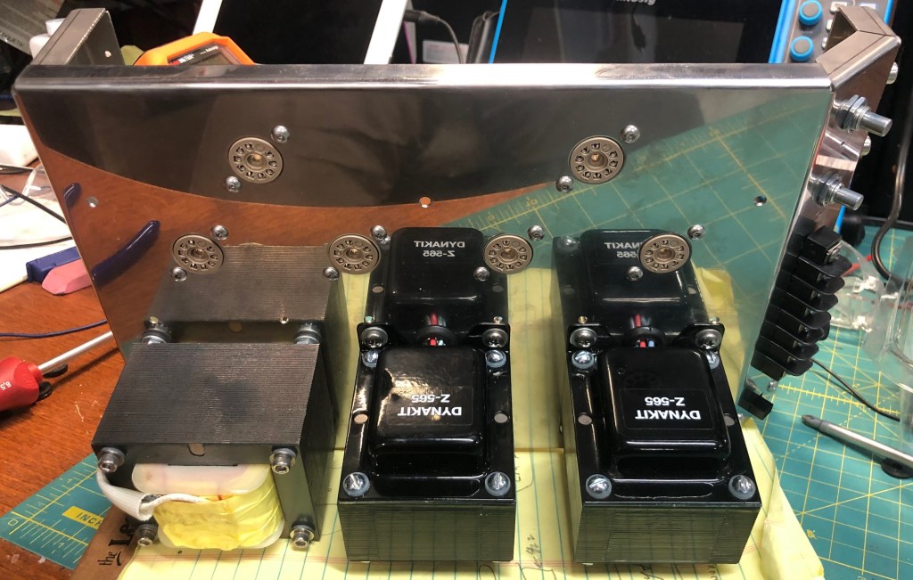
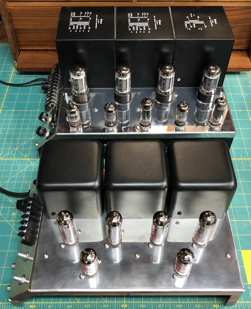
Below you can see the transformer labels, which contain the correct wiring diagrams of the Dynakit Parts PA-774 power transformer and the Z-565 output transformers. The labels were cut from black coated aluminum business card blanks and etched on a Glowforge laser.
The whole project was a labor of love and made no sense from a financial standpoint, but I have to say I smile every time I use it. All in all, the cost was kind of nuts. The rough parts expense total was about $720 (of course not counting untold hours):
- Chassis $200
- Transformers $200 (now would be $300)
- Tubes $80
- Transformer cans $80
- PCBs $40 (for 5 sets)
- Belkin tube sockets $20
- Other parts (caps, resistors, hardware etc.) $100
Below is a shot of the amp sitting next a real MC275. It’s so cuuute!
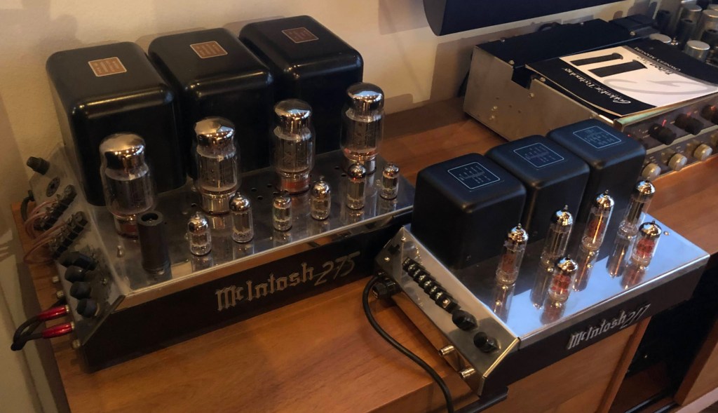
Now I just lurk in wait for some other McIntosh or antique HiFi aficionado to do a double-take when they see my “MC217” 🙂
Closing Thoughts
Now that this is complete, and for anyone who is thinking of a project like this:
- Get ALL your parts in hand and check all dimensions before sending off CAD files for cutting. Don’t trust part CAD models, even those from vendors. I got crossed up by a tube socket model that had the wrong spacing for mounting holes. Fortunately I was able to “oval” the chassis holes to make them work, and was lucky enough that the screw heads still covered my mistake.
- You can model all part positions, but also think about how you are going to screw it together and wire it up. If I was doing this again I would have added holes to PCBs to allow access to screw heads without removing boards.

Hello, I have a Mcintosh MC275 but it don´t have the output transformer “M-216-B”. I need to find it or do it. Can you help me? Thank you!
LikeLike
you have a cool Blog, added a link from my Blog to yours, cheers! and thanks for helping me our once again with that B&K PCB – Ray
LikeLike