
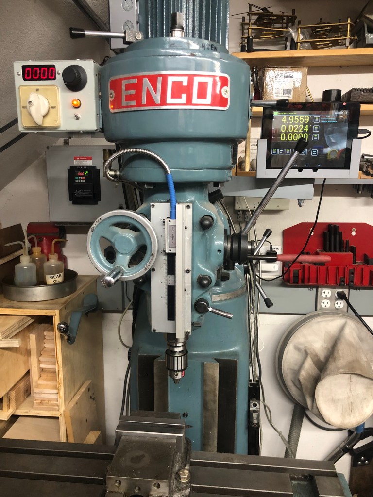
A while back, I got a nice deal on an early 90’s Enco 100-1525 milling machine. It’s a Chinese 2/3 size Bridgeport copy with an 8″x32″ table. This machine has a 3-phase motor, which I consider a plus because it means I can have knob-controlled speed by adding a VFD (Variable Frequency Drive).
Adding a VFD is usually not too complicated with typical two-speed three-phase motors, but this machine turned out to have a 4.3-to-1 speed ratio between the two ranges (unlike the typical 2-to-1 ratio). With a 2-to-1 ratio, it’s usually fine to run the motor only on the high speed range and then use the VFD for speed reduction. There is a small torque reduction at low speeds when doing this, but for home shop use, it’s fine.
But with the Enco mill motor’s 4.3-to-1 ratio, if I only drive the high speed motor coils and then try to dial down the speed to cover the slow range, the torque loss is too much. This meant I had to keep BOTH motor speed ranges and devise a way to switch between them.

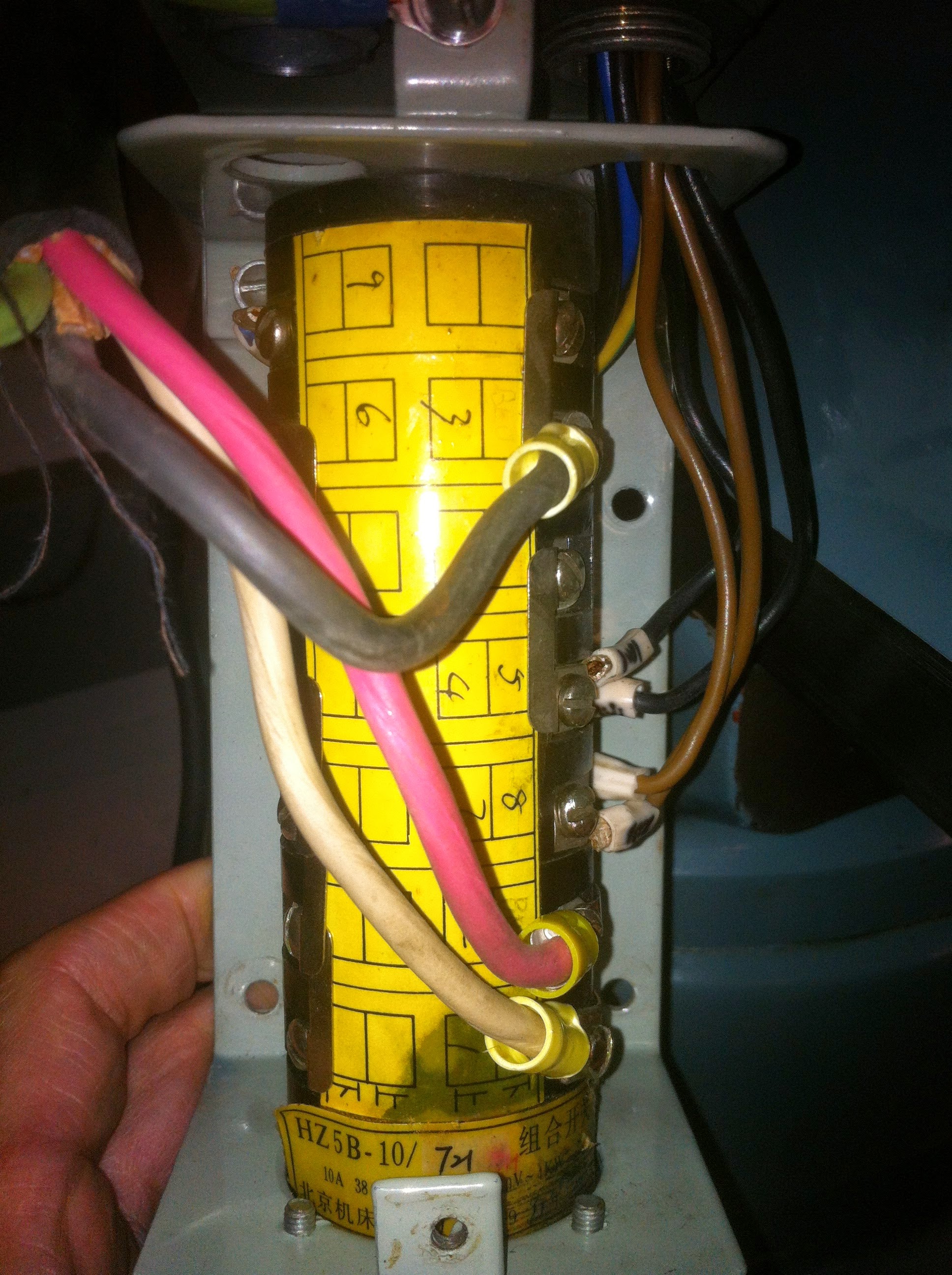
I started by tracing through the original drum switch on the mill. It had 5 positions: FORWARD HI, FORWARD LO, OFF, REVERSE LO, REVERSE HI.
The motor is a “Dahlander” style: https://en.wikipedia.org/wiki/Dahlander_pole_changing_motor
which requires some non-trivial connections for each of the speed ranges. In the low range, three nodes ( 1U, 1V and 1W in the above Wiki link) get powered in a “delta” connection. In high range, the 1U, 1V and 1W nodes get shorted to each other while the 2U, 2V and 2W nodes are powered in what is called a “double star”. Some head scratching was required to decode the old switch. The next step was to figure out how to duplicate the connections in an automated way.
It wouldn’t be silly to ask why I didn’t leave the drum switch as is and just power the mill from the VFD. The reason is that VFDs do not like to have switches between them and the motor. If I NEVER switched speed ranges while the mill was running, nothing should break, but I wanted a fail-safe idiot-proof design that did not depend on me always being on the ball. That leads to the following caveat.
I’D LIKE TO INTERJECT A WARNING HERE: THIS HOOKUP VIOLATES A BASIC RULE OF MOST (MAYBE ALL) VFD MANUFACTURERS. THAT IS NO SWITCHING DEVICES SHOULD BE CONNECTED BETWEEN THE VFD AND THE MOTOR. THE REASON FOR THIS IS THAT INTERRUPTING POWER TO A MOTOR WHEN A VFD IS POWERING IT CAN CAUSE A BIG INDUCTIVE SPIKE THAT CAN DAMAGE THE VFD.
I AM VIOLATING THE ABOVE RULE AND MOST LIKELY VOIDING MY VFD WARRANTEE. I’M INSERTING CONTACTORS BETWEEN THE VFD OUTPUT AND THE MOTOR, HOWEVER I HAVE THE VFD PROGRAMMED TO NEVER CHANGE THE CONTACTOR POSITION WHEN THE MOTOR IS MOVING. I AM CONFIDENT THIS PROVIDES SUFFICIENT PROTECTION, BUT IF YOU ARE UNCERTAIN, DO NOT DO THIS.
I did not violate the above rule lightly. I simply could not think of a cleaner more reliable way to accomplish the two speed ranges and prevent operator error. Note that this is only possible because the selected VFD (Hitachi WJ200) can be programmed and is able to store and select between two sets of motor parameters. I’m treating the two motor speed ranges like two separate motors. Not all VFDs are capable of this.

Link to PDF of Fig. 1: https://lensprojects.com/wp-content/uploads/2017/01/mill-vfd-diag-1.pdf
The key to the motor connection is the use of three contactors. In Fig. 2, one (CONT_1) is activated for the low speed range, while the other 2 (CONT_2 and CONT_3) are activated for the high speed range. For added safety, the contactors are driven from opposite sides of the VFD’s internal relay (AL1 and AL2) so that it is not possible for high and low speed to be activated at the same time.
Internal programming of the VFD (Hitachi WJ200-015SF) prevents any range changes while the motor is spinning. If the HIGH/LOW speed range switch is flipped while the motor is running, the motor remains in its current speed range until it is turned off and spins down. When the motor stops, the speed range is then changed.
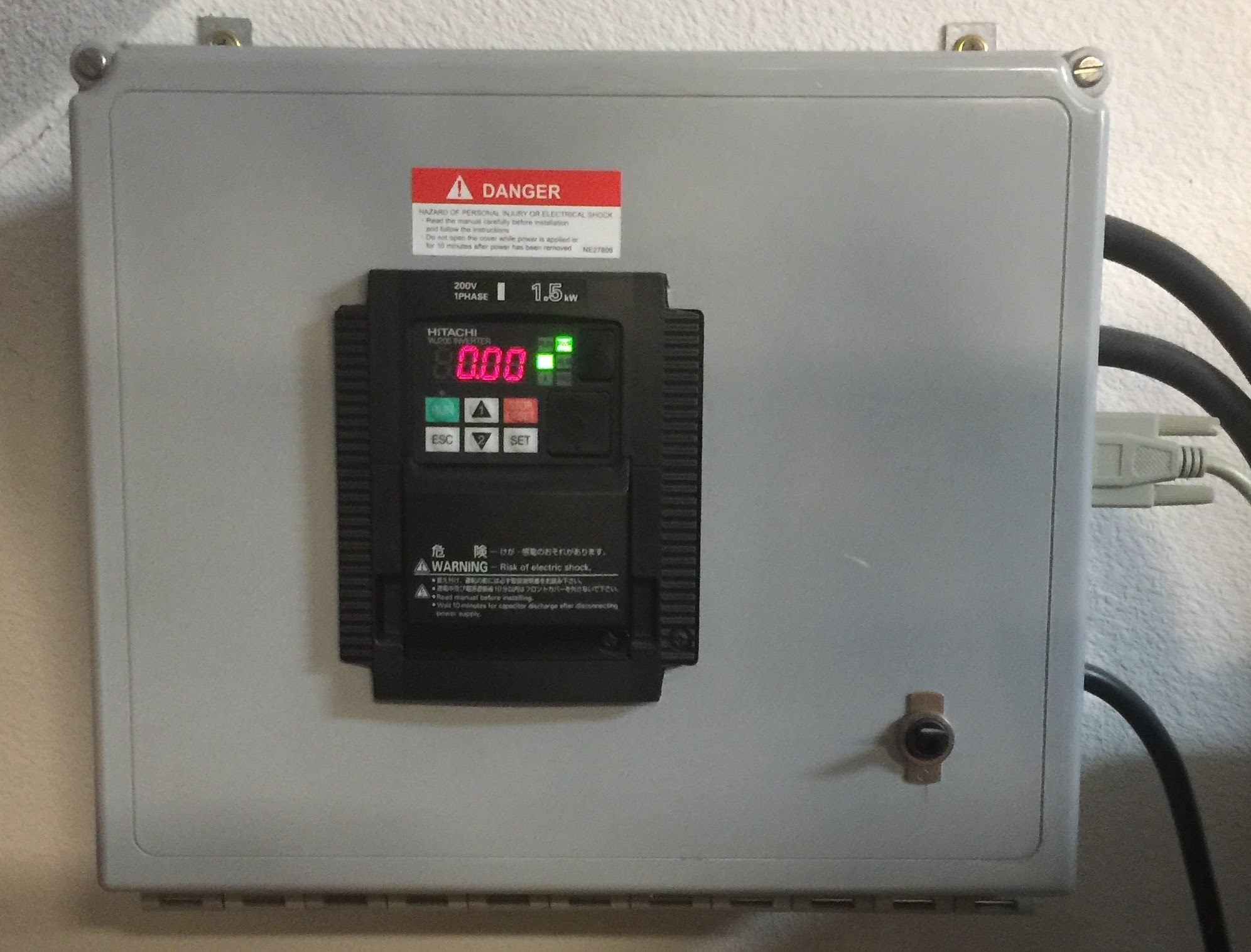
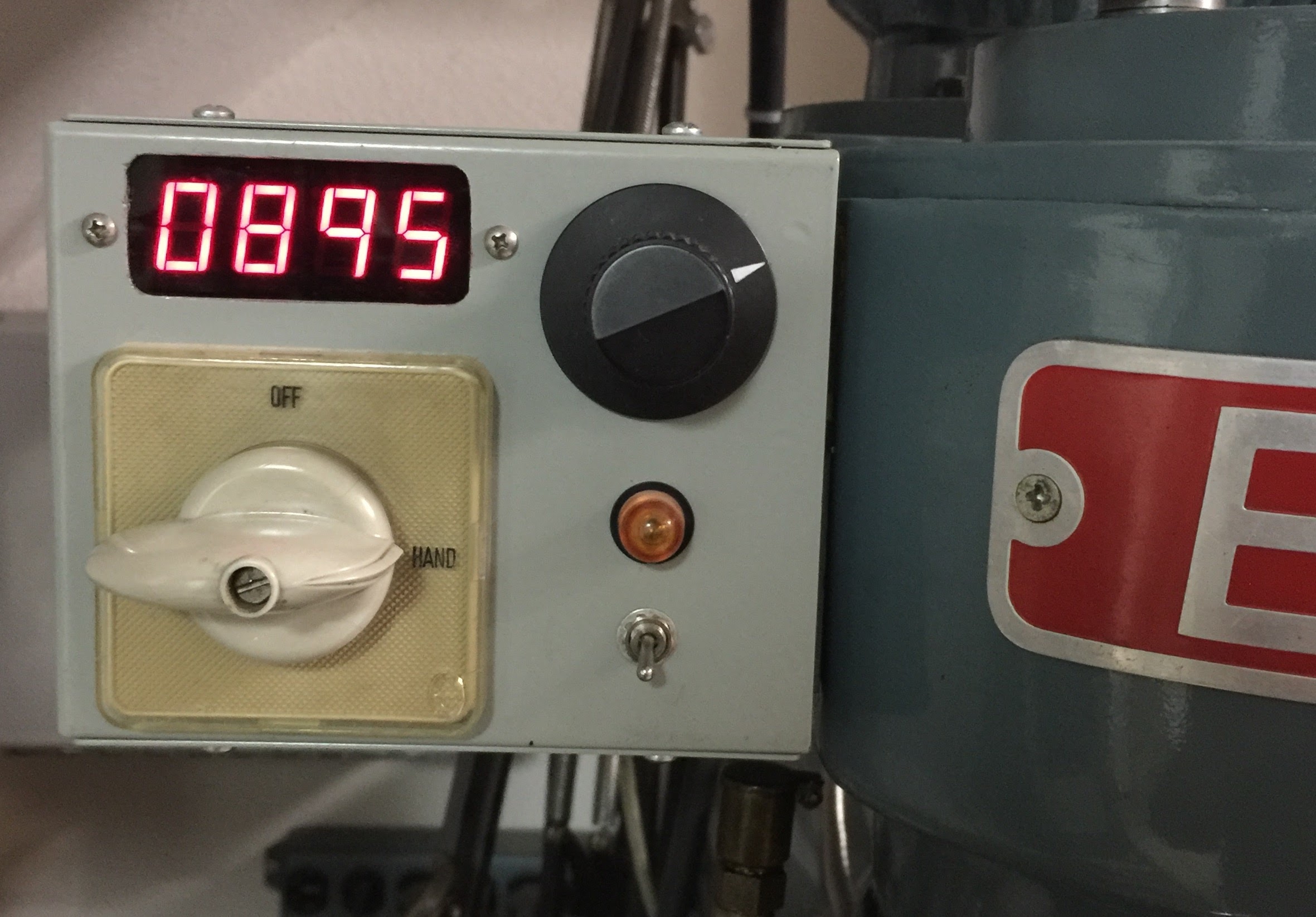
All the mill controls are housed in a small box attached to mill head. This box contains only low voltage controls that go to the VFD. It contains is no high voltage. High voltage is restricted to the VFD box.
This setup has been running flawlessly for about 10 (as of 3/’22) years.

Len,
I’d love to do the same thing to my identical Enco mill. Can you share with me a parts list for the rpm display, the P/N for the enclosure, the power supply and the rest of the components.
LikeLike
I to would like to do the same thing on my enco mill. More information would be helpful. I have been trying to figure out the VFD programming but I am lost could you make your program available?
LikeLike
Hi John – Unfortunately I didn’t write down what I did to program the VFD. I remember it *was* kind of painful to read to manual. Do you have the same model VFD that I used? Also, do you have the a weird motor like mine where high/low is not 2/1? If you have a normal 2/1 dual speed 3-phase motor, you don’t need to go through the hoops I did. If you have the same VFD as me, I think I remember finding a site where someone wrote a more readable set of instruction for programming. If you do have the same model, I could try to find that.
LikeLike
I have the same Enco 100-1525 mill with the same motor. It isn’t running as I haven’t bought a VDF yet. I have been looking at different VDF’s for the two motor control but haven’t found one that I could get my head around. If you could find that site you mentioned I would appreciate it. I will look also and spend more time reading the manual for the Hitachi before I buy it.
Thanks
LikeLike
I found this:
https://www.scribd.com/document/322893864/Hitachi-WJ200-Genric-Mill-Programming-Parameters
but it looks like you have to subscribe to get the whole document. I’m not sure if this what I used before.
Of course if you get a different VFD, this won’t do you any good. One idea might be to call Automation Direct and tell them what you want to do. They might be helpful and their prices are about as good as anywhere.
LikeLike
I also found this link that I saved some time in the past, so I’m pretty sure it helped me back when I installed the WJ200: https://www.cnczone.com/forums/spindles-vfd/130525-hitachi-wj200-settings-help.html
LikeLike
Awesome write up. I have the same machine and motor. You just saved me a ton of head scratching. Curious, Did you go with the 1hp Hitachi or larger rated drive? Seems the amps are right on the cusp of 1hp.
LikeLike
Thanks. I used the WJ200-015SF (rated for 2HP in CT continuous torque). It might not have been necessary to go that big, but I figured for the $50 price difference, I didn’t want to go through design and build to find out I needed to change the inverter later.
The other thing I remember was that programming was a pain. I wish I had taken notes on the programming, but unfortunately I didn’t. If I ever need to go back in, I’ll have to relearn the programming from scratch. I do remember there were some online programming write ups that were much better than the manual, but I don’t have links anymore. Hopefully Google will get you there.
LikeLike
Thanks Lens, I went ahead and ordered the 2hp. Kinda weird, Marshall Wolf called Hitachi and their engineer said to go with the 3hp. Did not make much sense to me. Anyways, on your main box I see a toggle switch that looks to have the main power to it, is that just a 240 volt toggle so you can power down the whole unit? Not a toggle that operates a magnetic contact?
LikeLike
I just picked up one of these mills and was trying to figure out how to put a vfd on it. From what you wrote out looks like I can still use a vfd like normal, but I would have to make sure to shut it of before changing speed or direction. Is that right?
LikeLike
Yes. You could continue to use the drum switch and just make sure you to don’t flip it with the machine running. It would simplify the hookup a ton.
LikeLike
I have the same machine, I bought it in 1992, yes it is 30 years old now and still works perfect. I use a rotary phase converter to run it, so I can take advantage of the high and low speeds and can quick reverse the motor for power taping.
LikeLike
I found this write up super helpful when adding the vfd to my machine. I used the simple method without all the contactors and just set it up with a low and high speed motor setting in the vfd with a toggle switch. Did not get into the barrel switch wiring at all.
LikeLike
TonyT, which VFD did you go with?
LikeLike
Went with the hitachi wj200 1.5 kw. The settings are a bit involved but not impossible. I just did a low high speed switch at the box with a little note on each switch not to touch while motor running. Since the vfd is on the wall I also have the hitachi controller with reostat so that I can change settings and stuff in front of the machine rather that on the vfd itself.
LikeLike
Can you show your set up? And can you tap in the machine still?
LikeLike
Hey Doug, Not looking like I can post pics in the comments. Will try to post on the facebook group for these machines. The setup is nowhere near as cool and thought out as Lens. What I did was wire to a magnetic on off switch to vfd and then from vfd to motor wiring pigtail in a j box mounted behind the mill. I did not touch the barrel switch at all. There is a control box mounted in front of the original two speed barrel switch so it makes it intentionally awkward for me to switch speeds on the barrel. There is also a low high speed switch at the control box on the wall with the vfd. Just have to remember to switch both while not running. I used the off the shelf hitachi remote controller but also ran another line to the control box on the mill that gives me a forward/ off/ reverse toggle then did forward reverse jog buttons. The jog through the vfd with this motor is a bit weird cuz the ramp up settings cannot be set to go bull bore right out of the gate or it will cause an error and shut down. Maybe a way to tweak this more but have not looked that much. Lens did a super nice job with his build so I would suggest following that more than mine but what I did does work well enough for what I do.
LikeLike
Doug, I posted the pics on the FB page
https://www.facebook.com/groups/3127640214216241
LikeLike
can we just use a 3 phase inverter before the switch? 110v single phase to inverter to machine switch?
LikeLike
The inverter makers usually say not to do this, because if you turn the switch off, or flip from forward to reverse, while the inverter is driving the motor or even if the motor is just spinning, there can be an inductive kick that damages the inverter. However, as long as you never operate the switch while the inverter is running, or while the motor is spinning, it will work. I went through my awkward design because I didn’t trust myself to always remember that.
LikeLike
Hello len… just starting to wire this up.. in regard to power in. 240v in. I have 2 hots and a ground. One hot goes to L1 and the other N? N is not a neural correct.
Doug kalous ________________________________
LikeLike
Can you show your set up? And can you tap in the machine still?
LikeLike
HI Doug – I’m not sure what you are asking for. I have pictures of the mill already. I can do live reverse on the mill, if that is what you are asking, but it’s been quite a while since I actually did tapping on it.
LikeLike
Yes thanks. Live reversal is what’s needed to tap. No issues with that?
Happen to have a bill of materials for this? I’m Really green on electrical schematic
Again thanks.
Doug kalous ________________________________
LikeLike
Yes, reversing on the fly is no problem. This reminds something I saw (online) on a drill press that would be very cool for tapping, but I never got around to building. Two microswitches are set up on an adjustable sliding rod mounting to the mill spindle or the front gauge so that they are triggered at a settable positions. They are locked with thumb screws. With this you run the tap down with the quill, and when the lower switch triggers at the set depth it tells the VFD to reverse. After backing out, at the top, the other switch returns the VFD to forward. With this you can tap with the just the quill and never touch the F/R switch. I’ll try to find where I saw this, but it was a long time ago.
To answer your other question, I don’t have any documentation beyond what’s in my blog post.
LikeLike
Very cool.. hey I’m trying to buy the power supply you have. Know the brand?
Doug kalous ________________________________
LikeLike
Lens42, thanks for posting your build and information for the rest of us. before i start ordering components i’d like to know With your setup is it possibly to tap on your machine? forward to reverse no pause between (tap in tap out)?
LikeLike
I got the parts from surplus places, so that won’t be much help. This is not the exact power supply, but it’s probably close: https://www.digikey.com/en/products/detail/mean-well-usa-inc./RS-15-12/7706163
The contactors can be expensive if you are paying new $ for them. Maybe eBay? Be careful to make sure the contactor coil voltage and your power supply have the same voltage. I think I may have made this mistake, because when I look now, it appears I used a 12V power supply with 24V coil contactors. It works so I’m not going to mess with it now.
LikeLike
The contactors I used are ABB BC7-30-10. If you search that on eBay, a bunch turn up at ~$30. You can use any contactor, but these are nice because they are small. Note that they are 24V, so if buying those, you want a 24V power supply.
LikeLike