I still have a Philips 212 turntable that I bought new around 1974. This turntable is a classic from the heyday of affordable, but high quality, Hi-Fi gear.

Over the years, my 212 developed all the ailments familiar to owners of these machines. The main power switch failed, and then the touch buttons stopped working. This post details my repair/modification project.
The Philips 212 was built before the availability of low cost integrated circuits, so everything inside is designed with discrete transistors. An advantage of this is the machine can be troubleshot and fixed without hunting down specialized components, but some parts can be hard to get. Surprisingly, the bulbs that light the buttons are particularly scarce. They are also, annoyingly, integral to the circuit operation so that when a bulb burns out, the problem is not just that a button no longer lights up when touched, the button itself also ceases to work.
To be blunt, the circuit has not aged well over the decades. I’m sure those Philips designers were clever chaps in 1971, but a design rule I learned early on is that circuit robustness is inversely proportional to the number of trim pots. The 212 has five trim-pot tweaks under the hood. I’m an old “analog” guy, so the decision to give up on the original circuit was not made lightly. I have no doubt this design made sense in 1971, but the more I stared at the circuit, a voice in my head became louder, telling me that a little micro-controller could run the entire machine in its sleep.


The Philips 212 schematic and service manual are linked here: philips_ga212_sm
STARTING OVER
Almost everything on controller board can be replaced by a micro-controller. I used an Arduino Uno clone from Adafruit called the Metro Mini.
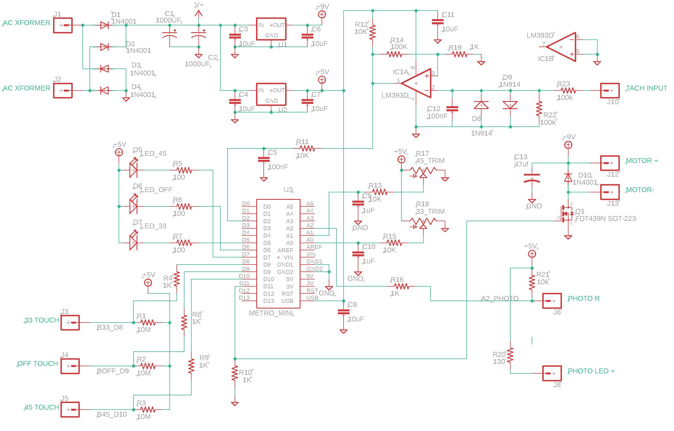
New Arduino-based Philips 212 controller schematic
DOCUMENTATION
Schematics, board files and Arduino code can be found at: https://github.com/lens42/Philips-212-turntable-arduino-based-controller
FUNCTION RUN DOWN
Touch button sensing for 33 RPM, OFF, and 45 RPM — The original touch sensing design used finger impedance to draw a uA (or so) current that activates a discrete transistor flip-flop. Since CMOS logic and micro-controllers have VERY low input leakage current, I now simply connect the touch buttons to Arduino inputs and 10MegOhm pull-up resistors to 5V. A finger touch overdrives the pull-up resistor and forces an input low. All speed select and OFF logic is Arduino controlled.
33, OFF, and 45 button illumination — I replaced incandescent bulbs with white LEDs, mercifully retiring the old circuit that utilized the bulbs in the control logic.
33 and 45 fine speed adjust — The Arduino clock is more than precise enough to give the new design sufficient accuracy without needing adjustments, but the Philips 212’s fine speed adjust is still desired for occasionally tuning records up or down. In order to retain the outer appearance and functionality, two of the old potentiometers are mounted on the new board and read by Arduino analog inputs A0 and A1. A small adjustment (up to about 2%) is made to the speed controller set-point depending on trim pot rotation.
Motor speed control — The original circuit drove the motor with DC, controlled by feedback from a tachometer winding. In the old circuit, the tachometer sinusoidal output was rectified and filtered to supply a DC feedback signal. Rather than replicate that, I square up the tach’s sine output with a comparator (IC1A, LM339D), and then measure period by counting time between pulses. Using tachometer period rather than amplitude provides more accurate feedback, won’t drift, and requires no trim pots. Motor drive is from an Arduino PWM output (D11) and a MOSFET switch (Q1) connected to the 9V supply. The original drive was DC, but I took an educated chance that the 500Hz Arduino PWM output will look enough like DC to the motor. Additionally, the rubber drive belt and inertia in the platter smooth out the short drive pulses. I also opted for simple proportional control of the motor, and not PID, figuring to try the easiest path first. Turntable speed seems very stable with this scheme.
Power — The original circuit is powered from a discrete transistor -9V regulator circuit that was adjusted by yet another trim pot. This was replaced with fixed-output three-terminal linear regulator ICs (U1 and U2) to supply +9V motor drive, and +5V to power the Arduino, LEDs, and buttons.
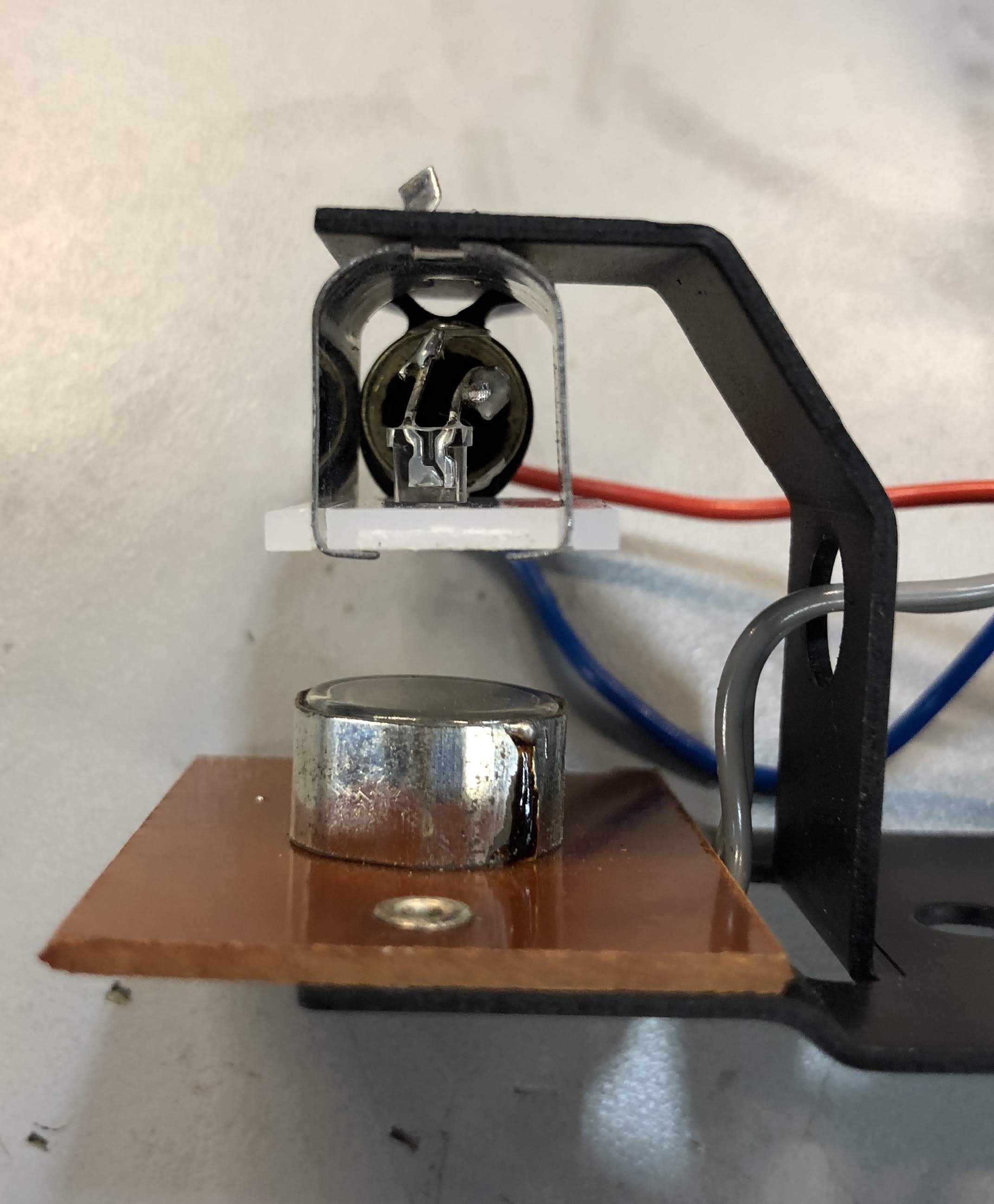
Auto-Shutoff — A photo-resistor/bulb combination (R404 and LA412 in the old Philips schematic) is mounted on a bracket inside the turntable. This is the auto shutoff module. When the tonearm reaches the end of a record, a thin metal vane interrupts light from a bulb that falls on the photo resistor. I replaced the bulb with a small white LED, though there would really be no problem leaving the old bulb in and powering it from 9V through 36 Ohms (as in the original schematic), but I wanted all the incandescent bulbs out.
In order to minimize mechanical changes, I broke open one of the bulbs and soldered an LED in the bulb base. You could skip the bulb and solder the LED directly to the socket, but I found the socket’s plastic unable to take much heat and gave up on that idea. In the new circuit, the LED is powered from 5V through 130 Ohms, and the photo resistor is biased from 5V through 10 kOhms. The photo resistor voltage is read by the Arduino A2 input and compared to a selected threshold (see photo_trip below)

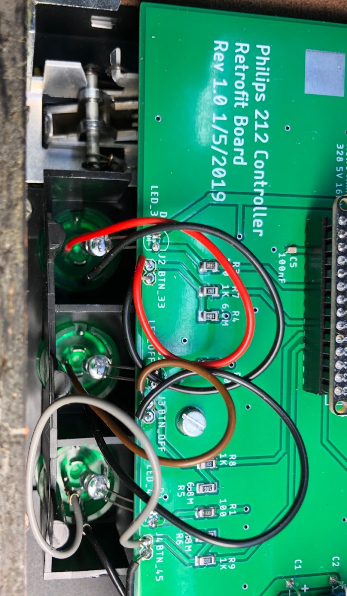
PCB and Mechanical — A new printed circuit board which matched the footprint of the original board was fabricated. This allowed easy board swapping with no special cutting or drilling. It was particularly useful to precisely copy the mounting hole locations and slot locations for the bracket that holds the speed adjust potentiometers. The new board also allows the button backlight LEDs to be mounted to the PCB, eliminating some hardware and wiring.
The schematic and PCB were designed in Eagle. I have an Eagle Premium license, so my 5″ x 6″ board was not a problem, but it exceeds the 4″ x 6″ limit for Eagle Standard. The circuitry could probably be housed in as small as 2″ x 4″ with a a different mounting scheme however.
Arduino Sketch – This is my first Arduino sketch for a real project (as opposed to blinking LEDs and other tutorials). There is probably a lot of badly conceived code in this, but it does run. I’m sure the hive mind can improve on it. Please feel free to let me know in the comments how it can be better. I won’t feel bad.
Calibration/Set-Up — Once the hardware is built and installed, control variables need to set. Since I’ve only modified one turntable, I don’t know if the values I chose will work for every GA212 (but you can certainly start with them). In order to perform set up, operate the turntable with the Arduino connected via USB to a computer running the Arduino IDE so that you can edit parameters and measure results.
I should note that I had no problem plugging and unplugging the USB connector to my laptop while the turntable was powered or un-powered. By the letter of USB law, you should not back-power a laptop USB output, which is sort of what I WAS doing when connecting my powered-on turntable to my laptop. But, since both sides (laptop and Arduino) are at 5V, there did not seem to be a problem. I can’t guarantee this will be OK every time. If you are worried about this, you’ll have to power off the turntable each time you upload a new sketch. I didn’t have the patience for that, but still lived to tell the tale. YMMV.
One other small note is that I put a small “mouse hole” in a corner of the plastic base so that I could run the USB cable out while machine was all together.
Four parameters need to be set. You’ll find these in the Arduino sketch:
t_err_range is the gain of the motor control loop. The code is such that a larger number equals lower gain. I set this by monitoring the PWM motor drive output with an oscilloscope to watch for oscillation in the pulse width, and testing different values (starting with 6000). The goal is to use the highest loop gain (lowest t_err_range) that is not so high that it causes oscillation in the PWM output. The t_err_range value I used was 7000. Unfortunately I can’t think of any way to test this without an oscilloscope, but if you don’t have one, you’d probably be fine just using 7000.
t_set_33 is the 33 RPM set-point for the motor controller. This number is the period of the tachometer output waveform at 33.3 RPM (in microseconds). Since the tachometer measures the motor (not the platter), which drives the platter via a belt and with a large speed reduction, the target period is not 1/33.3 RPM, but rather about 25ms, or a t_set_33 value of 25000. Note that any t_err_range adjustment requires a subsequent t_set_33 and t_set_45 readjustment since the control loop is not perfect and the actual output RPM depends both on the target period and the gain. The t_set_33 value used was 24650.
t_set_45 is the 45 RPM set-point for the motor controller. The same discussion in t_set_33 applies here. The t_set_45 value used was 17700.
The final values of t_set_33 and t_set_45 were determined by measuring platter RPM with a 60Hz strobe illuminating the strobe ring on the platter. My “strobe” was a white LED driven by a digital waveform generator with a 60Hz 20% duty-cycle square pulse. The generator frequency accuracy was more than adequate for this purpose.
photo_trip is the threshold of the auto-stop end-of-record photo sensor. A vane interrupts light to trigger auto stop, but the threshold may depend on the exact position of the LED and it’s intensity. I determined the correct threshold by serially monitoring the analog reading while moving the tone arm. The photo_trip value used was 800.
I had the boards fabricated by JLCPCB. https://jlcpcb.com/
In spite of the large board size, the price was less than $35 for 5 boards and slow shipping. I’ve had zero problems with JLC on about a dozen projects.


SPECIAL NOTES IF YOU DECIDE TO UNDERTAKE THIS MODIFICATION
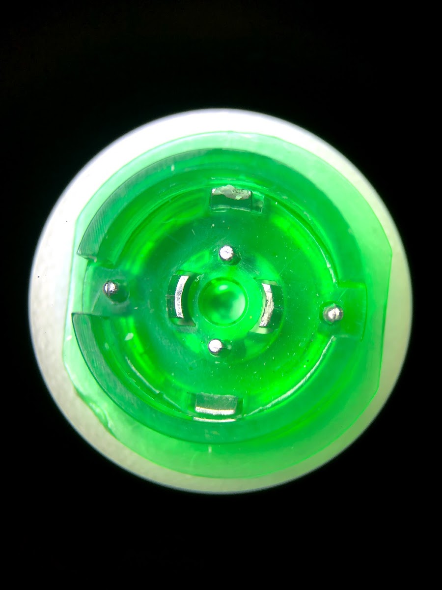
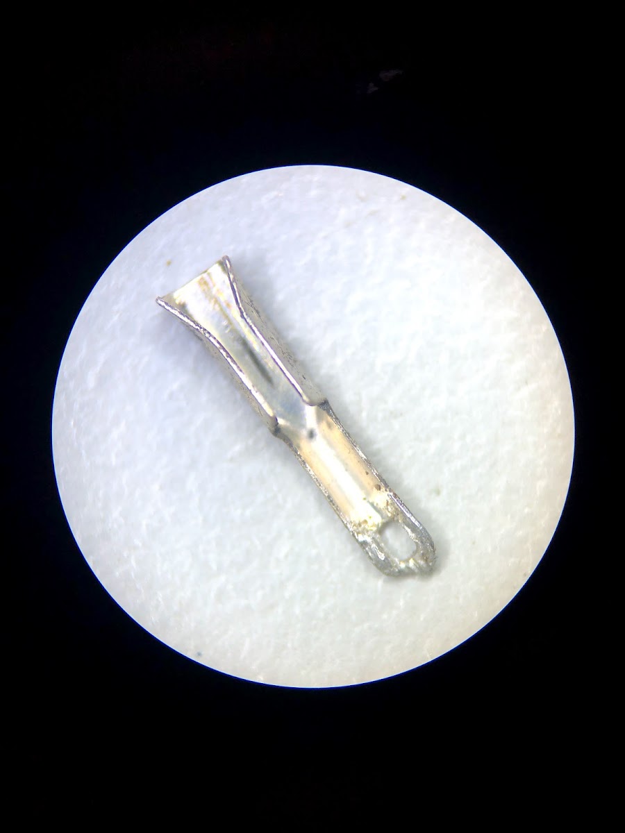
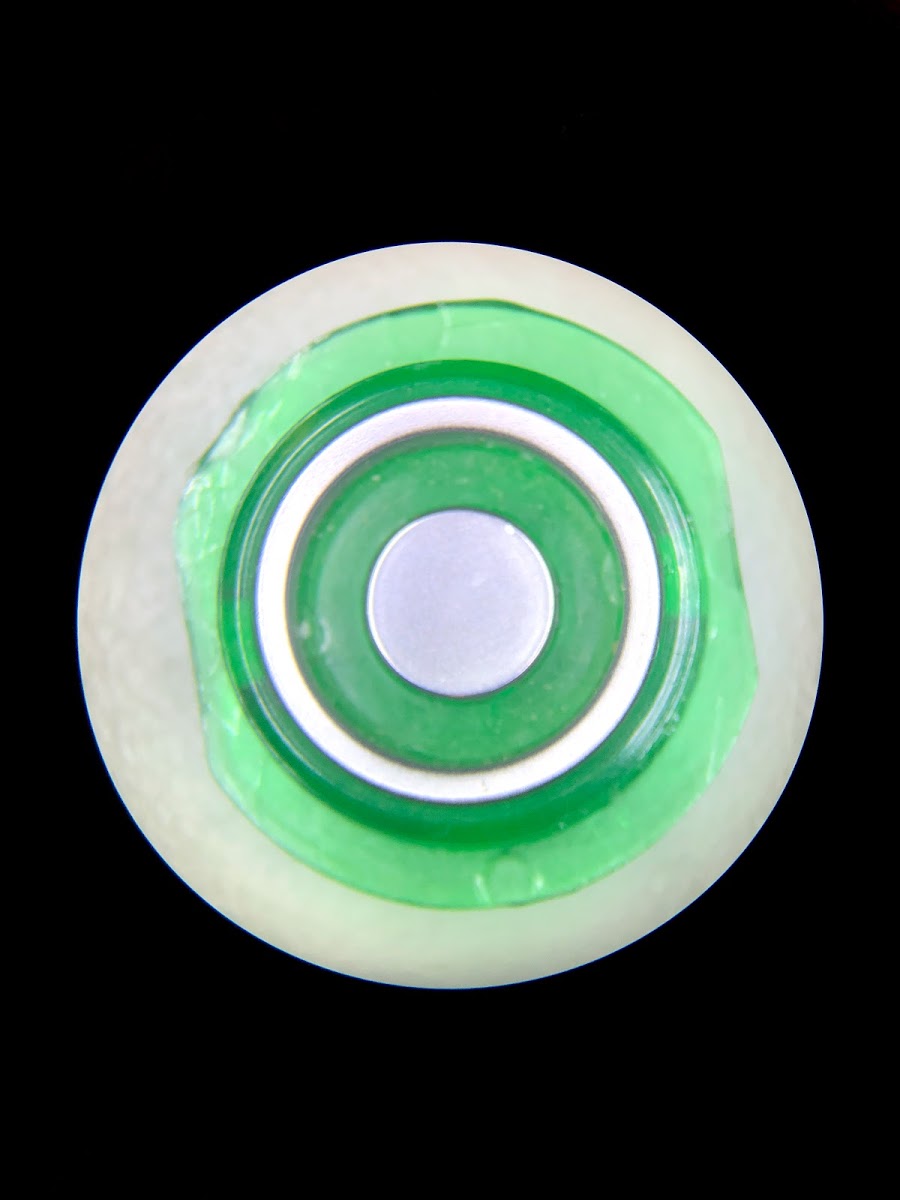
- When taking apart the turntable, be very careful when disconnecting the wires from the touch buttons. The parts of the buttons that look like metal (the ring and dot) ARE NOT METAL. They are plastic with a metallized surface coating that is easily scratched. Also BE CAREFUL NOT TO LOSE THE TINY CLIPS that attach wires to the buttons. In hind sight it may be a better strategy to NOT remove wires from the buttons at all, but instead unsolder or cut the touch-button wires from the controller board and leave the buttons undisturbed. Then just solder the wire ends to the new board.
Mistakes Made:
If I were to re-spin the board, this is what I would do differently (All these, except #5, are reflected in the latest board docs, but I have not fabbed rev 2 boards. My 212 works, so I’m done unless there is a big demand from readers.)
- Leave more space between AC transformer and Motor/Tach wire pads. There was no reason for 0.1″ spacing.
- Leave more space between the touch button wiring pads. Having them 0.1″ apart makes them more sensitive to board leakage.
- Add holes in the board at the center of the 45 and 33 RPM trim pots. It would help getting the pots lined up so the little knobs can be positioned more easily for reassembly.
- I put the Arduino in a socket header. It’s not super tight. I would add two holes so the Arduino can be secured with a tie wrap (as shown in my pics where I drilled the holes later).
- It’s not a “mistake” per se, but I thought about making the Arduino USB socket accessible (for future software upgrades?) without opening the turntable, but I didn’t do this)
It’s done!
So far this turntable has been working beautifully. As far as I can tell, the speed is at least as steady as the original, even with PWM drive to the motor and simple proportional feedback. I am very happy how this turned out, though it was a lot more work than I thought. I’ll leave it to others to decide if a Philips 212 warrants this level of effort to keep running. Though, now, the effort for others will hopefully be much less. This project was probably not justified from a purely economic standpoint, but it was an itch I had to scratch. The Philips 212 was a very nice, but not legendary, machine like Thorens, but it has good “bones”. If you have one that’s mechanically sound, but collecting dust because of controller problems, this may be a nice resurrection project.
I have not thought about whether I want to supply boards or parts. I’ll have to see what the reaction is to this post. It was certainly not a money making enterprise.
UPDATE 12/30/2021
I’ve sent people boards for about 5 turntables and have made new, Rev 3, board to clean up some things and make it a bit easier to connect the various wires.
UPDATE 3/24/2025
Thanks to Sika1965 in the comments, who has fixed a code problem that prevented the TT from starting at 45 RPM. Some other clean-ups to my clunky code were also made. This is now at the Github link as Philips_212_r6.ino. I have also cleaned up the PCB a bit and am now on rev 4.

Awesome write up. I’ve been in the process of resurrecting a 212 but recently ran into a snag in sourcing the C733 capacitor. This looks like it may be an easier way to get this turntable up and running. If you do decide to supply the board/parts I would be very interested.
LikeLike
Hi. C733 is nothing special. All it does is compensate the motor controller. The schematic says 820nF 250V polyester. Here it is from Mouser: https://www.mouser.com/ProductDetail/Panasonic/ECQ-E2824KB3?qs=sGAEpiMZZMv1cc3ydrPrF0%252BjlB8SXIRuS8SVaB6QeJw%3D
Why do you think C733 is the problem? Those caps don’t die very often.
In any case, if you want to go nuts like I did, I have four boards left over. They are rev 1.0 and will require the hacks shown in the photos. I can send you a blank one for $20 plus postage, or a populated one with everything except the fine adjust pots, LEDs, and the Arduino for $100. Let me know if interested.
LikeLiked by 1 person
Great work! These Philips machines do deserve it!
LikeLike
Sir, I recently stumbled upon this thread while trying to troubleshoot my turntable. I have no experience with andruino? I can do the soldering etc. A few questions:
Is programming the boars fairly straightforward?
I am fairly sure my pay is bad, and noticed that your pictures have a different unit in a different location. Is that something you changed?
LikeLike
Hi – please fix your typos. I can’t understand your last question.
LikeLike
How much would you charge to do this upgrade?! Amazing work!
LikeLike
I dunno, maybe $200 not counting shipping? There be would be a pretty high cost/risk to ship the turntable both ways. I’m sending a built board to someone who will do their own install. How do feel about wiring it in?
LikeLike
I’m struggling with a speed control problem on my 212 and I’m nearly at the point where I’m ready to take on this modification. However, I thought I’d first ask if you could lend any advice that might lead me to being able to repair mine using the existing circuitry? So far, my current efforts have yielded some improvement, but haven’t fixed the issue.
Here’s my post over at VinylEngine: https://www.vinylengine.com/turntable_forum/viewtopic.php?f=120&t=114998
LikeLike
I read your post over at Vinylengine. My suggestions: 1st, determine if the speed-up happens to both 33 and 45 rpm, that will narrow things down a bit. If the problem is only at 33, then that means the speed regulation works but the circuit associated with with setting 33rpm is out of whack.
BUT, I’m guessing the problem IS at both speeds and that it’s the RPM feedback that’s messed up. The circuit gets a feedback signal from the motor and drives the motor with more volts If the feedback goes down (to regulate speed). If the feedback signal is getting reduced by a leaky cap or other circuit problem, then the motor will speed up because the circuit THINKS the motor is slowing down when it isn’t. If you have a DVM, you can watch some of these voltages while the machine is running. If you see the motor feedback voltage not increasing when the speed goes up, that points to a problem.
LikeLike
Thank you, I will give that a shot. I think one of the local resale shops had some 45’s I can test with.
I do have a DVM and looking at the schematic I think that would involve testing voltage across the brown and black wires from the motor as those are apparently connected to the tachometer circuit. Is that correct?
LikeLike
Hello again, two big favors to ask if I may?
I’ve decided to go all in on using your board.
First; would you be willing to supply a detailed parts list? I was able to get the parts BOM out of the files you supplied and upon reviewing them I’m not sure how confident I am I’ll select the correct parts. Especially around the area of capacitors. There’s a few that have a different device listed than the value given, my plan was to reference value, but I wasn’t sure if the voltage should be the same.
Second; I think I’ve got the circuit board sorted out with JLCPCB, but would you mind double-checking my selections? The only one I went away from their defaults was on the surface finish.
Layers:2
Dimension:152mm*126mm
PCB Thickness:1.6
Impedance:no
PCB Color:Green
Surface Finish:ENIG-RoHS
Copper Weight:1 oz
Gold Fingers:No
Material Details:FR4-Standard Tg 130-140C
Panel By JLCPCB: No
Weight:320g
Flying Probe Test:Fully Test
Castellated Holes:no
Remove Order Number:No
LikeLike
Hi, thanks for the awesome write up. I’ve got an old (unworking) 212 that my dad bought as a teenager and now he’s handed it down to me in hopes taht I can bring it back to life. Any chance you’d still sell one of your leftover rev1 boards?
LikeLike
Hi – I have a few Rev 1 boards and also a rev 2 board. I can send you a blank rev 1 board (which will require hacks mentioned in the blog) for $10, or a rev 2 board (no hacks needed) for $20. If you like, I can populate a rev 2 board with everything except the metal bracket, pots (which come from your old controller), and Arduino, for $100.
LikeLiked by 1 person
Thanks! I’d be interested in the rev2 board (possibly populated). I’m sorry, I’m not too familiar with wordpress…is there a way to send you a private message so we can work out the details?
LikeLike
Hi jaminwillaims – After a bit of searching, I’m still not sure how to do private messaging here. The only thing I can think of is if you send me a comment containing your email, and I will NOT approve it, so it should not appear. Then I’ll contact you.
LikeLike
hi there, i’ll take a rev. 2 board if available. i’m located in the continental US. thank you.
LikeLike
not sure if i have to put my email in the comment body or not, but just in case, it’s jmigeed@gmail.com
LikeLike
Hi.. I’m retired, and now do what I’ve done for 30 yrs.. collect, restore and sell vintage audio.. esp rebuilding turntables and record changers. question I HOPE you can answer.. As you might know, if the power switch of a 312 or 212 doesn’t have a “snubber cap” wired across it, like Philips only started including in the later year models, when you turn on/off, you get that loud “POP” through your speakers. I’ve seen eBay sellers, selling new switches that include the wafer type capacitor..but nowhere online can I find the VALUES for that type of cap… I’m sure it’s something simple that could be bought at Digi-Key for pennies.. Do you know the exact values for that wafer type cap? uF and voltage ? I assume the uf value is low enough that polarity doesn’t matter… PLEASE send me a message to my email, unc80@yahoo.com if you can help? I have a clients 312 tables almost complete except for installing a snubber cap to the power switch. Thanks so much.. Greg
LikeLike
Hi,
Are you still selling made up Controller boards (Rev 2) for the PHILIPS 212 TT? I would be willing to pay for a populated board, minus the donor components.
I have a 212 that is not currently working but I’m sure I could get it going again if I had one of your controller boards. The TT still has its original controller board, so I will have no problem getting the donor components.
If you are still making your Controller boards, please let me know. I would happily pay $100 + shipping for you to populate the board and send it down to me. (I live in New Zealand)
Thanks for your time and I look forward to hearing from you.
Gordon.
LikeLike
I think I could do the upgrade with the board ready to go but would still need maybe help which I think there is enough to do in this article. I hope you are still available.;
LikeLike
Hi Scott – I sent you a email
LikeLike
I apologize for not being prompt on my reply, anyway I just purchased a new open end cable to phono male ends to my 212 and to phono 1 on my old McIntosh preamp tuner, etc. Anyway hooked it up, sound clean and wonderful but only right channel and stuck on 45 rpm. After I figure out the lost channel, I will return to phono motor speed, etc. but meanwhile just wanting to know if you are still active, etc. I am retired and will find the time to get things back and running. Hope you are well with all the mess going on. Hope to hear from you. Thanks, Brewer
LikeLike
Hi Scott – Yup, still here :-). I just sent you another email with some troubleshoot ideas. – Len
LikeLike
great project, do you still have a board ?
LikeLike
Yes. I will contact you via email.
LikeLike
Hi lens,
I have two GA212’S. I would like to mod one of them with rhe the Andruino board. I would like you to do the work for your asking price. I originally bought this TT in 1974 and sold my system in ’81. I love vintage audio and have wanted to resurrection both of my Ga212 that I have acquired. The one that would be sent is functioning, but the incandescents on the speed are defunct. Only thing I know that is failing.
1st question:
Are you still doing the work on them?
2nd question: Are you willing? Price?
Thanks so much,
Chris Fruit RN BSN
LikeLike
Hi Chris – Yes, I’m still working on these. I’ll email you details.
LikeLike
Wondering if you have any rev 2 boards still available. I have two 212 turntables I bought on eBay that were not working and I have “restored” them both to 100% functional. I plan to give them to my two sons but this upgrade really interests me.
LikeLike
Yes. I have boards. I sent you an email.
LikeLike
Hi Lens,
Thanks for your inspiration!
I have the same itch, and love the 22GA212. I have used your original idea and made some improvements, using a 72Mhz STM32F103 (Arm Cortex M3).
For motor control I use Pulse Density Modulation at 33 kHz. I tried your 500Hz PWM, but my 212 motor became noisy doing that. With 33kHz PDM it became totally silent.
I double rectify the tacho and process that output via ADC2. I use a wide range software PLL to determine the RPM. The RPM range is now excellent and I have decided to implement 16RPM, 33RPM, 45RPM as well as 78RPM. This method also saves quite a bit of circuitry (comparator etc)
The STM32 is a 3.3V device. For the green eyes i put 2 diodes in series with the 10 Mohm pullup. This makes the detection very nimble. After some SW debouncing it operates way better than the original circuit. Just a brief touch with a dry finger is enough.
Friendly regards,
Willem van der Brug (Philips engineer)
Holland
LikeLike
Hi Willem – This really sounds like you took this to the next level, and from a Philips engineer no less! Thanks for the comment. Will details be visible in future?
LikeLike
Hi Lens,
Thanks for your stimulation. My project is not yet finished, but when it does I’ll share details. I am indeed a (retired) Philips engineer, but I never worked on the 212 off course, before my time. I have been system architect of the Philips SACD1000 multichannel SACD player, quite a different beast.
One extra remark to implementation of the 212 firmware. I did notice in the original circuit that the automatic stop at the end of the record uses the first derivative of the LDR value. So basically the circuit looks at the arm starting to move faster in the exit groove. I think this can be emulated in software quite well, I will try and report on it. Your fixed ADC value for LDR detection may not be robust, certainly not between various 212’s.
One more remark: I have found that the DC motor of the 212 already makes 100+ RPM when driven with 5 Volt. I have thus removed the original 50Hz transformer (humming at 50Hz, hence mounted in rubber grommets) of the 212 and replaced it with a very small (hum-free) SMPS which feeds both ATM32 and DC motor.
KR Willem
LikeLike
a brief video. sorry, narrated in Dutch
LikeLike
Very cool. If you are looking for features to add, one thing that I thought would be nice is a way to optimize parameters (motor drive gain, rpm set points, etc.) without having to open up the turntable. It would be cool to be able to do this wirelessly over Bluetooth. These sorts of things are beyond my skill level at this point, and I have other projects that outrank going back to “fix” a turntable that currently works.
LikeLike
Hi Lens. For parameter tuning I use a USB cable to the microprocessor SDE dongle. Can easily tune everything while the table is playing. I am now implementing a non-linear PID algorithm for RPM control. Simple Proportional-only is not perfect enough. The table now has 4 speeds: 16, 33, 45 and 78 RPM. 16 is chosen by tapping 33 a second time and 78 by tapping 45 a second time. I have replaced the 33/45 adjust screws with 2 LED’s. One is “Quartz Lock” when the RPM becomes accurate and the second LED indicated “alternate speed” i.e. 16/78. I see no need for speed control. As the tacho readout is digital in Quartz clocked timer ticks, speed is super accurate.
LikeLike
Hi Willem – This all sounds amazing! Do you own 16 RPM records? I’m also curious what deficiencies you found with proportional control. It’s seems to work fine on the units I’ve modified (only 4 however), though I did not look much beyond 33 1/3 RPM performance.
The only other comment I have is that the speed controls aren’t necessarily for achieving accuracy, but rather to allow tuning a record to an accompanying instrument that can’t easily be tuned, such as a piano. I also wanted to stay true to all the 212 functions.
LikeLike
Hi Lens,
Ah, the adjustment for an accompanying instrument is a good reason. I myself do not use that.
I do not have 16 RPM records but I know that they exist. I added 16 and 78 RPM just for fun.
The main deficiency of proportional-only control is that the Ist-speed never exactly becomes the Soll-Speed. There is always a fractional difference. With a small I component this can be avoided.
For all 4 speeds I use different coefficients for the P and I. I am using the Internet-recommended manual method which is loosely based on Ziegler-Nichols as starting values for P and I. Basically you increase gain until oscillation starts and then tune it back by some percentage, I use 30%. All 4 speeds are quite stable now.
I have added some code to start I-control only after P-control has settled. It makes the behavior much more subtle. Also my software PLL on the tacho adjusts to lower-noise smallband tuning when it approaches the desired speed, after using noisier wideband PLL before that time.
For now I’ll leave it at this. I’ll now complete the 212 with a nice MM element and cabling and start using it for a while 🙂
LikeLike
Hi Lens,
Did you also find that the end groove detection is tricky? I have found records where the exit groove is a quarter inch or even less. On those records and with the tolerance in LDR lighting and LDR value it is IMHO not possible to use a fixed ADC switchpoint for end groove detection. After quite some experimentation I now use a differential ADC algorithm. Every 1 msec the algorithm uses a 200 msec previous ADC value and compares. Above a certain threshold it switches off. For noise reduction I average 64 ADC values every 1 msec. The ADC runs at the PDM speed of approx 64 kHz.
200 msec is approx 1/10th of a revolution so now even a microscopic exit groove suffices. Took 2 evenings to get this working right…
LikeLike
I haven’t had problems, but I have not tested it as rigorously as you have.
LikeLike
Thinking about your comment, now I think I finally understand why the auto-stop vane has a triangular shaped slit with a change in the slit angle about half way through the slit. The change in the slit angle will cause a sharp change in the light rate of change right at that point. So detecting dLight/dt would trigger right at that precise point where the angle changes, and of course be independent of light intensity. Can you make your Arduino code available? I probably would have to make major changes for the slower Metro Mini, but I think it’s probably still fast enough for the job.
LikeLike
I lost the answer to your question on proportional control somehow. I have found that Proportional feedback only leaves a difference between Soll and Ist values of the RPM. A small I component in the PI control solves this. The original Philips circuit BTW was proportional only. Another reason for the speed adjust pots..
LikeLike
Len, many thanks for the board and help! So here is an update on my two 212’s. I got the board fully wired up in the 212 and working yesterday. In my opinion it is now “optimized” and functions better. The lights appear brighter and respond quicker. My other 212 which is still unmodified did have an issue with one record that has about a quarter inch exit groove. My fix was to move the positioning of the stop sensor light until it was optimal. It was a small adjustment. Note the record I have with the small exit groove is The Lonesome Jubilee by John Mellencamp.
LikeLike
Great! I think Willem is correct about the best detection scheme for auto-shutoff would be to sense the rate of light change, rather than a fixed threshold. If can figure out how to do that, I may send out an update. OTOH, it may be wiser to not fix something that doesn’t appear broken.
LikeLike
Hi – would you have any of the boards left? Love to buy one. Decided to relisten to all my vinyl, but the turntable is basically dead press the power button and one of the speed controls, and that lamp lights, but remove my finger it goes off. Motor doesn’t turn at all. Thought of troubleshoot, but ran across you solution. I think a new board like yours makes sense, but since you’ve got the design I’m hoping you have a spare board to sell..
LikeLike
I agree with don’t fix what isn’t broken. For just a few 212 ‘tables it is also OK to manually tune a few things to get things optimal. The dLight/dt algorithm IMHO makes the mechanism totally table independent. For any table it always works exactly at the point where the arm starts to move faster. I see it now reacting after just 1/10th of a turn after the exit groove starts, wherever it starts, just as long as the triangular part of the optical arm assembly is in ‘view’ of the LDR.
Unfortunately I am not familiar with the Arduino/open source environment but I’d be happy to mail you the source code of the Auto shutoff part if you give me an email address. The other code I cannot share as some parts of it are not owned by me (the tacho PLL)
LikeLike
hi,
As Lens said, you took the already GREAT project to a “next level” !!!
Do you have any plans to make a available (comercially or not) ?
If it’s possible, i would like to see the code for the “auto shut off” implementation you made.
Cheers and Thanks in advance !!
LikeLike
Hello
I have several 212 I would like to restore one with your assembled arduino board, you can send me mail
Thank you
LikeLike
Wow, this is a great project. I bought my 212 new, and used it for several years even though the light for the 33 button went out early on, it still worked fine. Eventually I stored it away in the garage until now, after a renewed interest in music. (I retired recently)
Anyway, I have several arduinos sitting around, and dont think Id have problems finding the other parts. Soldering the surface mount resistors, etc will probably be the hardest part, but I have an ok soldering station, so I’ll get it done.
Turns out the Shure phono cart thats in it is selling for $200 these days, so it would be great to get this thing working. If you’re still making them, Id love to buy a board and a parts list from you. If you have them, and if you could, put the board for sale on ebay and give me a link. Include the cost of shipping and whatever fee ebay would charge you.
If not, I’ll pay however you like. Thanks!
LikeLike
Hello,
Is there still a Rev 2 print without parts available for my Philips 212
LikeLike
Wow, as a vintage stereo guy, I find this to be very interesting, as I have been buying a couple of 212, and 312 to play with. So far just switches and belts to replace. I think your board would be an excellent upgrade especially if you make them all set up to just solder the wires in. I can follow a schematic but know nothing about that controller. Being retired with enough money to just purchase it complete, makes sense to me. I hope you are considering possibly mass producing the boards all set up to wire in.
LikeLike
So, I have 2 312 and one 212, and I was wondering if your board works in the 312 as well. Started to tune a 312 up and realized there are no numbers or anything on the board, you have to painstakingly kind of trace everything. Not fun for my old eyes. While trying to set the first task to get the power up to -10.0 volts, I couldn’t, bad caps maybe, or need a new power supply. Or maybe I will just buy one of your boards, if it will work, even if it makes the 312 a 212 I could go with that.
Gary
LikeLike
So I started to tune up a 312 and basically couldn’t get the voltage up to -10.0 as noted. Replace the caps or get a new power supply, or both. Hopefully the caps will do the trick. Who designs a board with no numbers or anything on it. What a pain to trace that out.
Does your board work for the 312 as well, or can I just convert the 312 to a 212 using your board? Will try replacing those nicely colored caps that I dealt with in a McIntosh 1900. They fell apart.
So if you could get me some pricing on your boards, I would appreciate it. I don’t mind soldering, but the less I have to do is probably better. Thanks.
Gary
LikeLike
Have a 212 that doesn’t power up how to ck this could it be the switch?
Any help would be greatly appreciated thank you
Larry
fender98@pacbell.net
LikeLike
The 212’s power switch is a mechanical push on / push off. Often the mechanism breaks so the switch no longer can be pushed. Is that what you are seeing? There used to be a guy on eBay selling replacements.
LikeLike
Both of my 212’s had bad power switches. One was stuck and did not work, the other worked randomly. I bought two replacements on eBay and they worked fine.
LikeLike
Hi Lens 42,
Please let me know if you could prepare and sell one complete and ready to connect circuit board for the GA212, in such a way I can install it here.
You can email me , if this suits you better
Kind Regards
LikeLike
Sent you email
LikeLike
Hi lens42,
Great project and design! I inherited my favorite uncle’s GA-212, Pioneer SX-1010 receiver, and JBL L-100 speakers and they have great sentimental value to me. After cleaning the black goo that used to be the belt, I find the GA-212 is stuck on 45 rpm. Rather then try to debug this, I’m hoping I can get one of your stuffed boards – any possibility you can sell me one?
Best Regards,
Rich
LikeLike
Are you by any chance located within driving distance of Sacramento Ca.?
LikeLike
Hello, I enjoyed your post about your 212 — I wish I had those kinds of skills with electronics! I’m trying to get the auto stop working on my 312, and I was wondering if you could help me with two very basic questions that I just don’t understand how to do. Could you interpret “the supply voltage must be -10 V in regard to the chassis” and “the voltage across the LDR should be 2.5 V”? I’m ready to measure these with my multimeter — I’m just not sure what components to measure. Thanks in advance for any guidance you can provide, I appreciate it.
LikeLike
Hi Tony – Not having worked on a 312, I assume it is saying the supply voltage is -10V (as opposed to -9V for a 212). That voltage runs the TT and is measured with respect to ground, which mean the chassis. The comment about the LDR (this the light-dependent resistor that senses the vane interrupting the light bulb at the end of a record) They are saying there should be 2.5V across that device, but I’m not sure if they mean when it is illuminated by the light bulb or not illuminated because the vane is blocking light. I forget which one of those (lit or unlit) happens at the end of the record.
BUT – before you get deep into troubleshooting make sure that the lightbulb that shines on the LDR is lit. It may be burned out.
LikeLike
I appreciate the guidance. Do you think the best place to measure that supply voltage is one side of the largest capacitor on the board (near where I think power comes to the board)? I have attached the black lead to the ground on the table. Btw, my 312 has an LED for the LDR, so thankfully that eliminates the potential lightbulb issue.
LikeLike
hi lens , great project.
I gave it a go with my old 212. the board is in, all went fine but I have the following issue.
33 rpm seems to be working fine. adjustment, starting , all good.
45 rpm motor does not start. I also dont measure a voltage change on the motor when choosing 45 speed….
funny is however. if I start with 33, then select 45 it is working. but just a bit to slow. whilst the adjustment is max.
I checked all components. it looks al good at first sight.
do you have any tips fixing this?
thank you
LikeLike
reuploaded the sketch, now it works. strage 🙂
LikeLike
TO: lens42
I was wondering if you ever produce a few of the boards you made and put them up for sale. Still would like to try one. Have both a 312 and 212, wasn’t sure which one you did make it for. Please let me know.
LikeLike
Any chance you have any Rev.3 Boards on hand? Thanks
LikeLike
Interested in a Rev 3 board to revive my father’s old 212.
LikeLike
Seems I remember reading these turntables were designed to run win 110v instead of 120v, would a Variable Voltage Converter be helpful to provide 110v?
LikeLike
It won’t matter. The internal voltage is regulated. You can use 120 with no conversion.
LikeLike
also Interested in a Rev 3 board here. are they still available??
LikeLike
Any chance there are anymore Rev 3 boards around?
LikeLike
I have the exact same problem with a GA312: the speed is going up (to about 100RPM) on both 33RPM or 45RPM.
I have already adjusted the main voltage as per the Service Manual (to -10V), and also replaced the 2 eletrolitic capacitors (and some other ceramic related to the speed control circuit), but still have the speed-up issue.
I’m willing to try your suggestion to measure the motor feedback voltage, but I’m not Shure where to measure it. It’s just measure between the two tachometer wires ? Or is it somewhere else ?
thanks in advance, and congrats for the superp project !!!
LikeLike
Yes, the tach output wires would be a place to start, but the problem is more likely downstream from there, after some rectification and filtering. I’m not familiar with the 312 to point out specific parts. The signal from the tach is AC and the original TT circuit rectifies and filters that to make a speed FB signal. Problem might be a leaky cap or bad diode in that part of the circuit.
LikeLike
You naild it ! I saw the return wave from the motor’s tachometer and it showed an increasing voltage / frequency sine wave (as expected). So, I followed the rectifing / filtering tacho section and found a “broken” transistors (BC548B). Changed it, and now I have an “almost” controlable speed on both 33,3 and 44 RPM. I said “almost” because the speed keeps floating 5% up and down…. Not sure if thats normal… maybe there are more to fix ?? BTW on your new arduino based board you can keep the speed more stable ??
Thanks in advance !!
LikeLike
Silvio, 5% speed variation is not normal. There is still some problem. It could be that the feedback gain is too high and the speed controller is oscillating. If it’s that, you’ll see the speed oscillate up and down around the correct speed at a regular rate. Unfortunately, I don’t know how to adjust a 312. My Arduino circuit is very stable, but I don’t think it will work on a 312.
LikeLike
great thread and hard work! I have had my 212 since the early 70’s. I’m all in. Is the rev 3 board available?
LikeLike
I finally revived my 212 thanks to your design.
But I have the same problem as Patrick Kriek.
The first time I put the power on it, the 45 did work immediately. After turning it on a second time it didn’t. It did through the 33 selection though.
Also, both speeds are slightly too slow at maximum potentiometer setting, but that is a matter of fine tuning.
I still have 4 PCBs left for those interested.
LikeLike
I just finished a 2nd build and also see the 45RPM problem on this. I suspect this can be a software fix but I don’t have an answer yet. I will of course post as soon as I do,
LikeLike
I found the problem.
t_diff = t_per – t_set is not always calculated correctly because t_diff and t_set are not defined as ‘ long’ while ‘t_per’ is.
So: long pwmValue = 0; long tachDiff = 0;
Why the 33 rpm did always start correctly is beyond me.
I found this out by monitoring ‘ live’ with the Arduino attached to the laptop. To be sure, I made a cable where the power supply was interrupted.
Further polished up some code, although there is potential for more improvements, but for me it’s fine as it is.
Speed tuned with Spotity playback because the strobe indication was not working properly. The constants t_set_33 and t_set_45 were therefore also given a different value.
LikeLiked by 1 person
Can you send me the updated sketch so I can post it here?
LikeLike
If you still have spare boards, let me know. I’d like to try it on my GA212 and also GA312. Thanks in advance.
LikeLike
Hi Silvio,
I have some PCBs spare.
LikeLike
About the PCBs, contact me please: ‘silviorf ‘ at ‘g’.
LikeLike
Hoi Lens,
Sorry voor de late reactie, maar hier is de code die voor mij werkt:
#define LED_OFF 6 // “OFF” LED drive output, LOW = on
#define LED_33 5 // “33” LED drive output, LOW = on
#define LED_45 7 // “45” LED drive output, LOW = on
#define BTN_OFF 9 // “OFF” touch button input
#define BTN_33 8 // “33” touch button input
#define BTN_45 10 // “45” touch button input
#define TRIM_POT_33 A0 // Analog input from trim pot to fine tune 33 RPM
#define TRIM_POT_45 A1 // Analog input from trim pot to fine tune 45 RPM
#define OPTO A2 // Analog input from auto-off photo resistor
#define TACH_IN 2 // Input pin for tach output from motor
#define PWM_OUT 11 // PWM drive output to motor
#define DEBOUNCE_TIME 10 // Debounce time in milliseconds
#define PHOTO_TRIP 700 // Threshold for end-of-record auto-off photo sensor
#define TRIM_OFFSET 512 // Offset fine trim reading so center rotation = 0 (512)
#define T_SET_33 24000 // Target period for 33 RPM (was 24650)
#define T_SET_45 16550 // Target period for 45 RPM (was 17700)
#define T_ERR_RANGE 7000 // Sets gain of motor control loop
#define N_OFFSET 84 // PWM output that drives motor at 33.3 RPM
byte stateOff = LOW; // Current state of LED_OFF output, start LED_OFF low (on) at power up
byte readingOff = LOW; // Current reading from BTN_OFF input, start BTN_OFF low at power up
byte state33 = HIGH; // Start 33 RPM off at power up
byte reading33 = HIGH;
byte state45 = HIGH; // Start 45 RPM off at power up
byte reading45 = HIGH;
int trim45; // 45 RPM fine trim pot value
int trim33; // 33 RPM fine trim pot value
int photoValue; // Auto-off photo sensor value
int t_set; // Tach period target value for the currently active RPM
long pwmValue = 0; // PWM outout to motor
long tachDiff = 0; // Tacho difference to compensate
volatile unsigned long tachPeriod;
unsigned long tachMicroseconds;
long lastDebounceTimeOff = 0; // Last time the OFF touch button changed state
long lastDebounceTime33 = 0; // Last time the 33 touch button changed state
long lastDebounceTime45 = 0; // Last time the 45 touch button changed state
void setup() {
Serial.begin(115200); //run when troubleshooting
pinMode(BTN_OFF, INPUT); // Set up OFF, 33, and 45 buttons
pinMode(BTN_33, INPUT);
pinMode(BTN_45, INPUT);
pinMode(LED_45, OUTPUT); // Set up OFF, 33, and 45 indicator LEDs
pinMode(LED_33, OUTPUT);
pinMode(LED_OFF, OUTPUT);
pinMode(TACH_IN, INPUT);
pinMode(PWM_OUT, OUTPUT);
attachInterrupt(digitalPinToInterrupt(TACH_IN), tachometer, FALLING); // Set external interrupt for tachometer period measurement
tachPeriod = 50000; // Start with long period to ensure startup
} // setup
void loop() {
trim45 = analogRead(TRIM_POT_45);
trim33 = analogRead(TRIM_POT_33);
photoValue = analogRead(OPTO);
// Code for “OFF” button and LED
readingOff = digitalRead(BTN_OFF);
if (readingOff == LOW && millis() – lastDebounceTimeOff > DEBOUNCE_TIME) {
stateOff = LOW;
state33 = HIGH; // Turn off OFF and 45 LEDs
state45 = HIGH; // Turn off OFF and 33 LEDs
lastDebounceTimeOff = millis();
} // if readingOff..
digitalWrite(LED_OFF, stateOff);
// Code for “33 RPM” button and LED
reading33 = digitalRead(BTN_33);
if (reading33 == LOW && millis() – lastDebounceTime33 > DEBOUNCE_TIME) {
stateOff = HIGH;
state33 = LOW;
state45 = HIGH;
lastDebounceTime33 = millis();
} // if reading33..
if (state33 == LOW) {
t_set = T_SET_33 + trim33 – TRIM_OFFSET;
} // if state33..
digitalWrite(LED_33, state33);
// Code for “45 RPM” button and LED
reading45 = digitalRead(BTN_45);
if (reading45 == LOW && millis() – lastDebounceTime45 > DEBOUNCE_TIME) {
stateOff = HIGH;
state33 = HIGH;
state45 = LOW;
lastDebounceTime45 = millis();
} // if reading45..
if (state45 == LOW) {
t_set = T_SET_45 + trim45 – TRIM_OFFSET;
} // if state45..
digitalWrite(LED_45, state45);
// When the tonearm reaches the record end, the photo resistor is interrupted and the OFF state is set
if (photoValue > PHOTO_TRIP) {
stateOff = LOW; // Off state, OFF LED on
state33 = HIGH; // Turn off OFF and 45 LEDs
state45 = HIGH;
} // if photoValue..
// Read period from tachometer and control motor
tachPeriod = constrain(tachPeriod, 5000, 50000);
tachDiff = tachPeriod – t_set; // Corrected calculation
pwmValue = map(tachDiff, T_ERR_RANGE, -T_ERR_RANGE, 255, 0); // T_ERR_RANGE = 7000
pwmValue = pwmValue – N_OFFSET; // N_OFFSET = 84 is pwm value for speed 33
pwmValue = constrain(pwmValue, 0, 255);
if (stateOff == LOW) {
analogWrite(PWM_OUT, 0); // Hold motor off during OFF state
} else {
analogWrite(PWM_OUT, pwmValue); // Else drive motor with PWM output
//Serial.println(pwmValue);
} // if stateOff..
Serial.println(photoValue);
} // loop
// Determine time between pulses from tachometer
void tachometer() {
tachPeriod = micros() – tachMicroseconds;
tachMicroseconds = micros();
} // tachometer
LikeLike