The number one component failure in antique electronic devices is old electrolytic capacitors. Most troublesome are the “can” type multi-segment capacitors. These are hard to find and can be quite expensive. More importantly, even if you find a replacement, it’s likely to be “old stock” and not certain to last since the some aspects of their “clock” started ticking when they were made, not when you start using them.
My approach has been to “re-cap” failed can capacitors with modern capacitors of equal or better ratings. This is cheaper, and also more reliable as long as high quality caps are used. Many think this can’t be done without cutting or damaging the can and impacting the appearance of the equipment. This would, of course, not be desirable in equipment where the can caps are visible, such as old McIntosh power amplifiers.
The rest of this post will show how to re-cap cans so they look completely original when done.
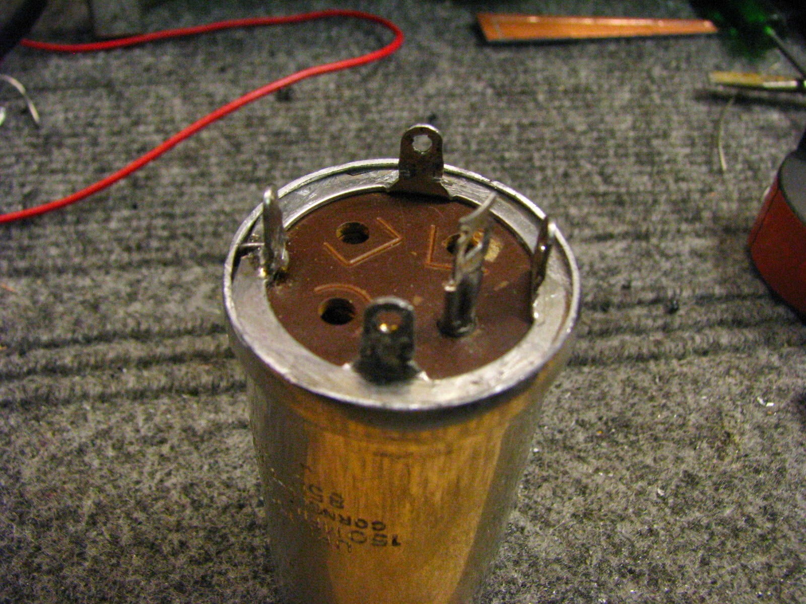
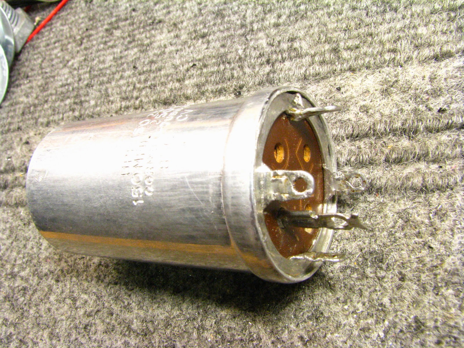
After removing the capacitor, the first step is to carefully file off the flange that holds the terminals in place. Go slowly and take off as little material as possible. Note that following pictures are not from the same capacitor – I’ve done this a dozen or more times, but didn’t get a series of shots from one operation. Another thing to note in the below photo, I didn’t remove the paper sleeve before filing. That was a mistake.
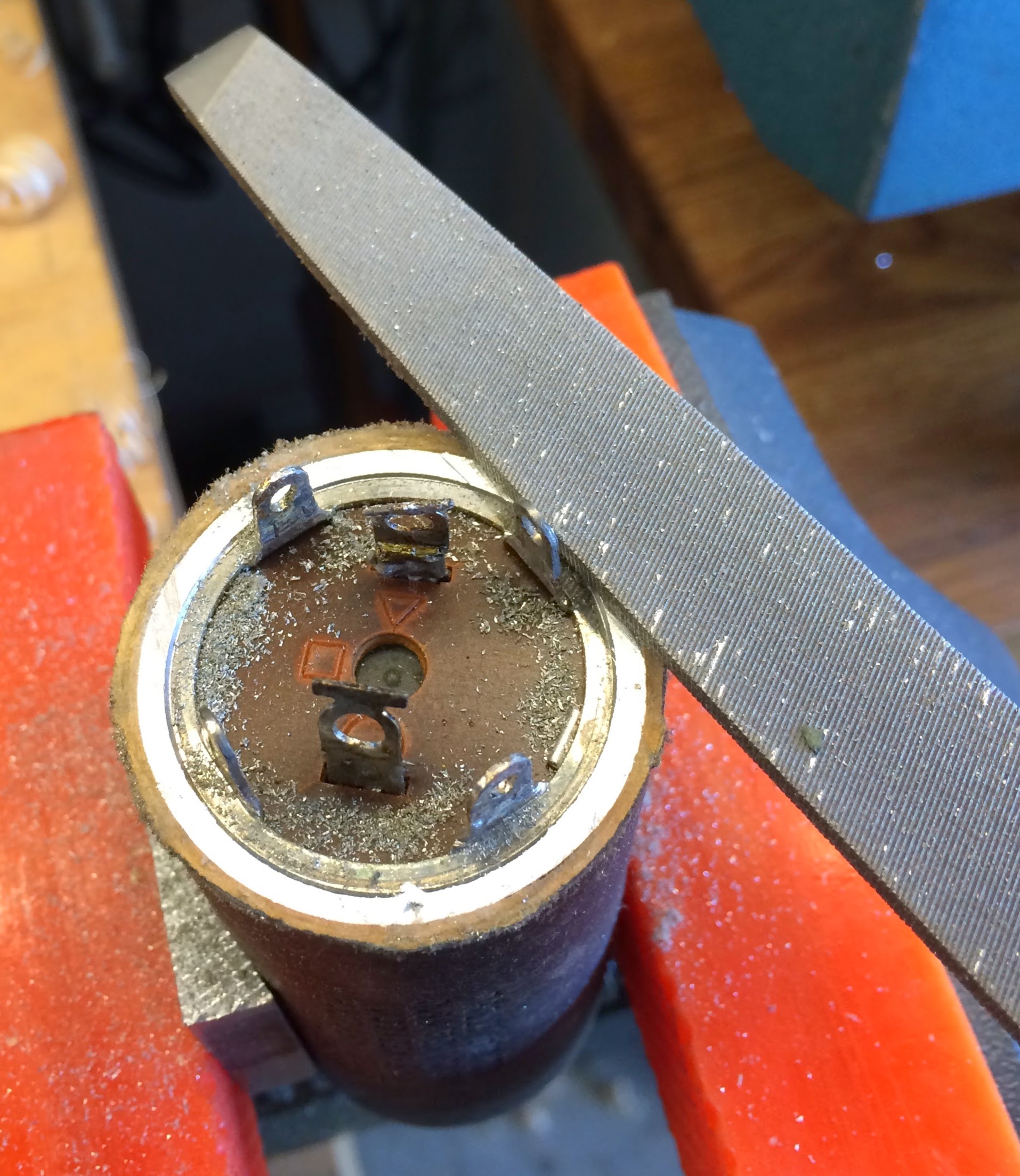
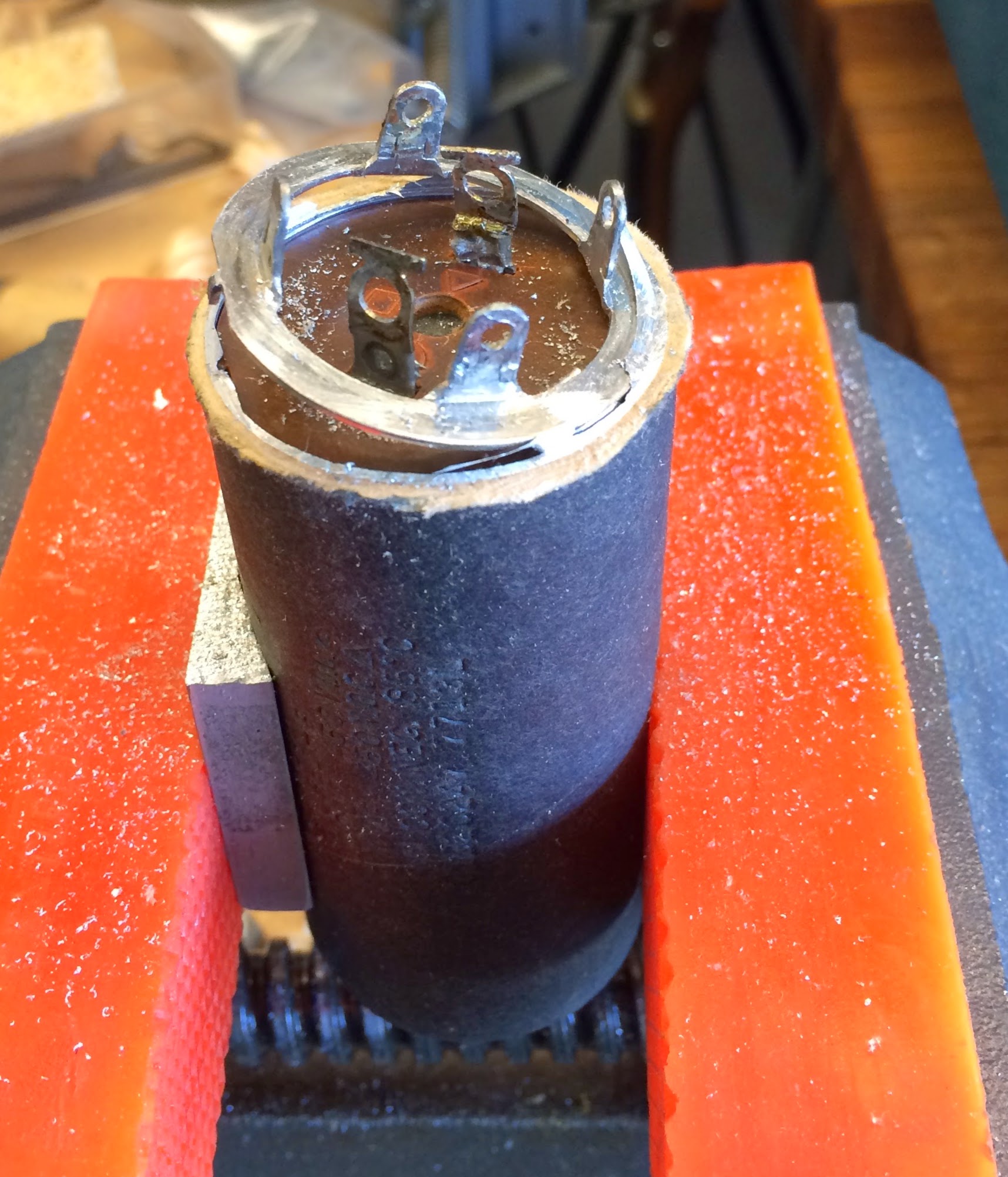
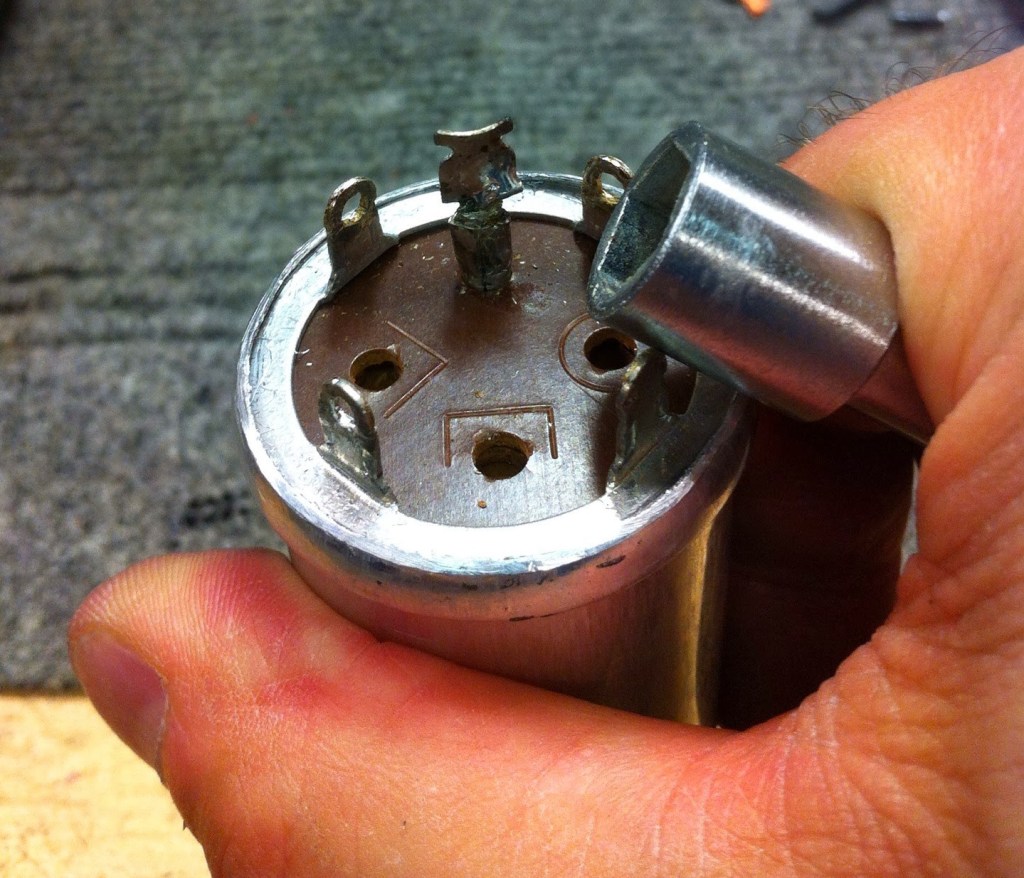
Once you’ve gotten just enough flange filled off, pry up the ground terminal ring and the phenolic terminal board. You’ll have to cut wires underneath to release these parts. Be careful because all of this gets reused. Also note the V-block and plastic vise jaws to hold the can without damage. Even better would be to drill a wood block with a hole the same diameter as the cap, and slice the block to make a conforming set of vise clamps.
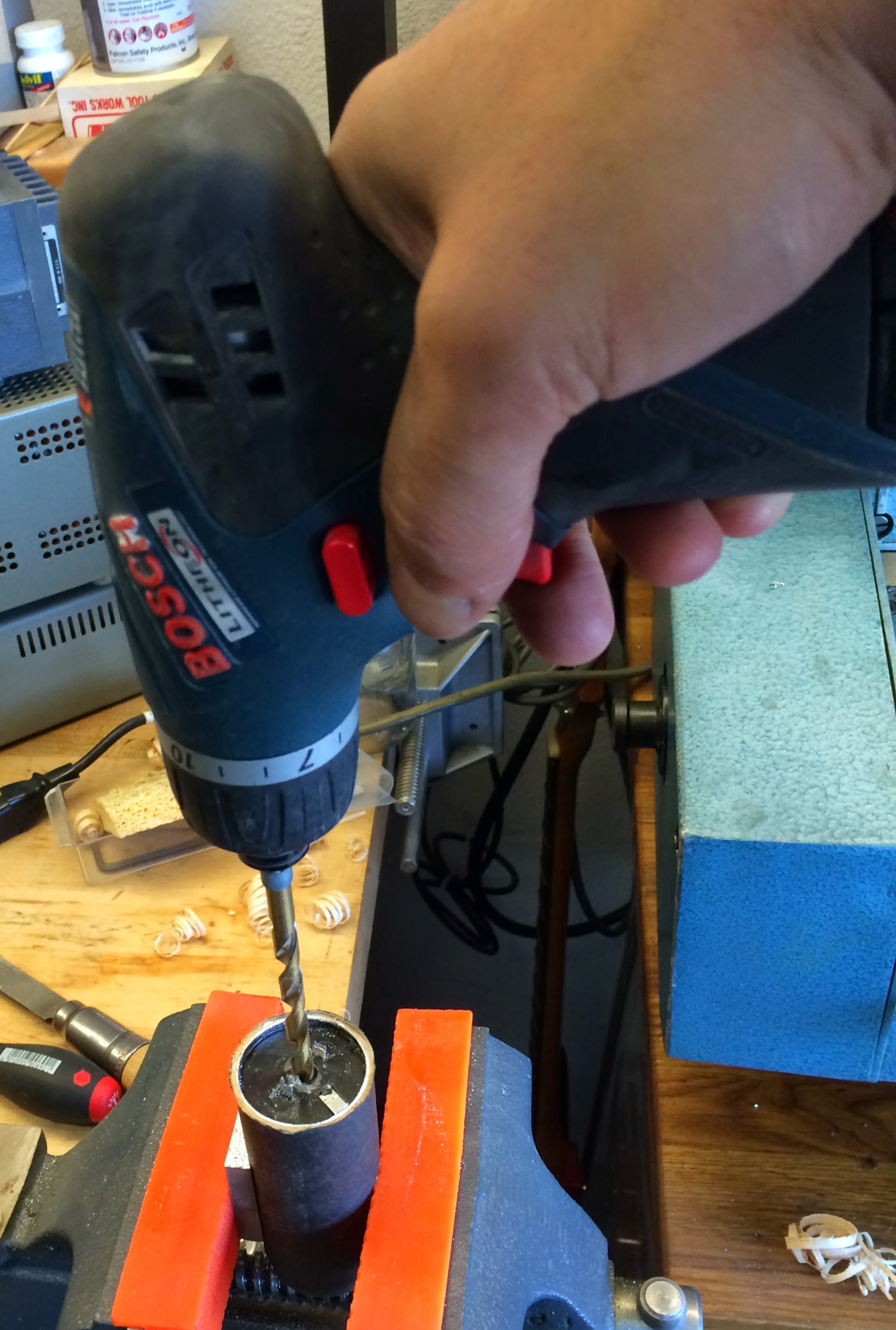
When you have the ring and phenolic disk(s) out, drill a hole into the casting goop to fit the lag bolt in the next step. Don’t be shy. The cap internals are already history.
Next thread in a lag bolt. This provides a handle so the whole casting slug and old caps can be yanked out. This has never required a very hard pull, but if it’s stubborn, some heat will probably help.
Below shows all the bits removed, ready to recap.
I didn’t seem to have a photo showing the new caps soldered in. The caps can be axial or radial with insulating tubing over the wires that are not grounded to the case. It doesn’t matter what it looks like inside as long as the appropriate leads are insulated from each other and the case. DO NOT USE ELECTRICAL TAPE! I usually use teflon tubing.
The new capacitor (or capacitors for a multi-segment rebuild) can be soldered to the terminals from the back, or what’s a bit easier (but slightly more visible) is to drill a tiny hole at the base of each terminal and thread the cap lead through and solder to the base of the terminal on the outside.
Once the can is back together, the end needs to be crimped over to hold everything together. I made tapered collar on a lathe that I use as a form. I gently hammer the the cap (protecting the top with a wooded block) into the taper. You can accomplish the same thing (with slightly rougher finish) by gently hammering and burnishing the flange with a round tool.
Cap bottom end after crimping with the tapered collar.
After crimping the end, I put a bit more “roll” to the edge by burnishing with a round tool like a nut driver.
Below is the finished cap. The bottom is not rolled over as much as the original, but once it’s reinstalled in the equipment (in this case, a McIntosh MC240) it is essentially impossible to tell that it’s been re-capped.
One thing I should add is that, for very high voltage capacitors, you may have trouble finding modern replacements. One solution is stack two caps in series with balancing resistors as shown here: https://www.nmr.mgh.harvard.edu/~reese/electrolytics/
That’s it. I hope this proves useful.

After installing 4 new electrolytic aluminum can capacitors in a Mcintosh 240 amp, do you initially apply a lower voltage and then gradually increase it?
LikeLike
Hi Rafael – For caps that are REALLY new (not new old stock that has been on the shelf for decades) you should not have to slowly ramp the voltage. Slowly ramping is for “reforming” old electrolytics and, to be honest, I’ve never done it because I don’t install old capacitors in repairs. It not worth the trouble.
LikeLike
Thank you for your advice. I agree that it is not worth reforming and installing old capacitors. The problem these days, however, is to tell if the new ones are really new when purchasing. I have some Mcintosh amps that require four aluminum can electrolytic caps, and even buying them from a reputable source is questionable, since there is probably limited demand for the twist lock ones. In any event, I appreciate having taken the time to answer my inquiry. Best regards, Rafael from sunny Puerto Rico
LikeLike